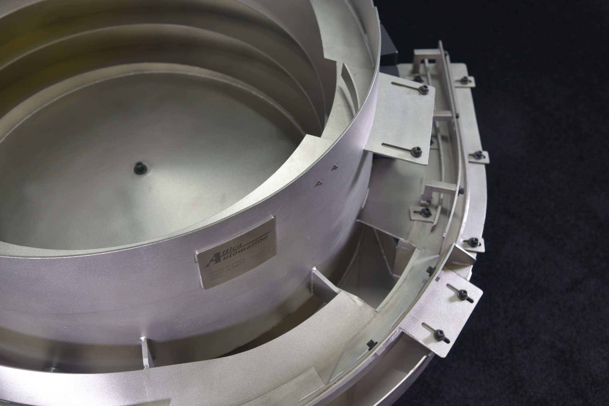
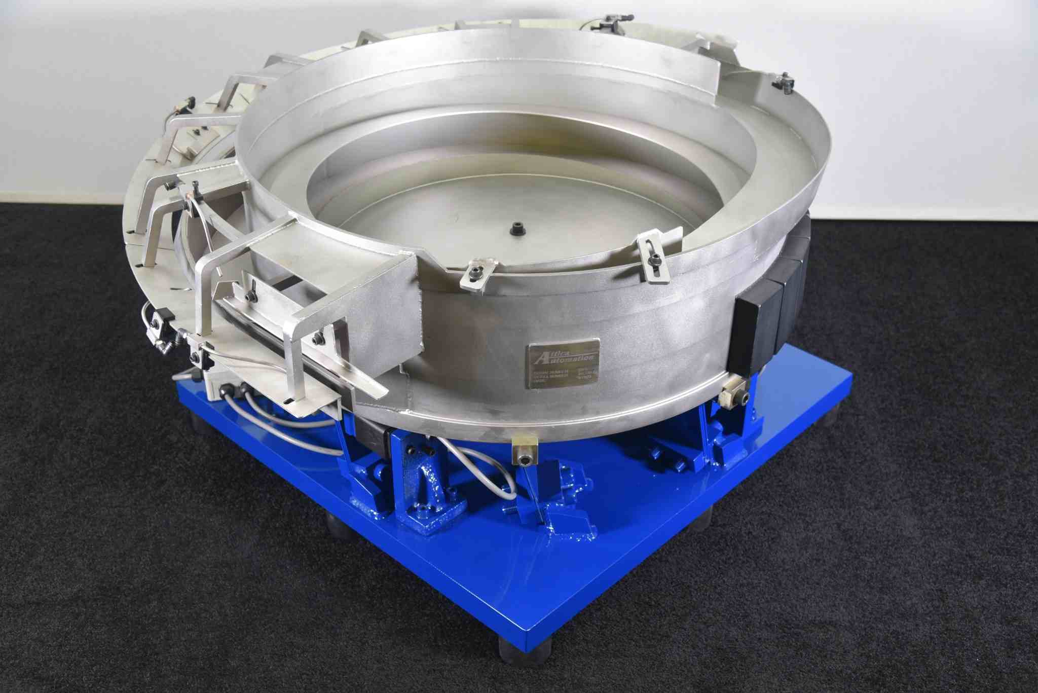
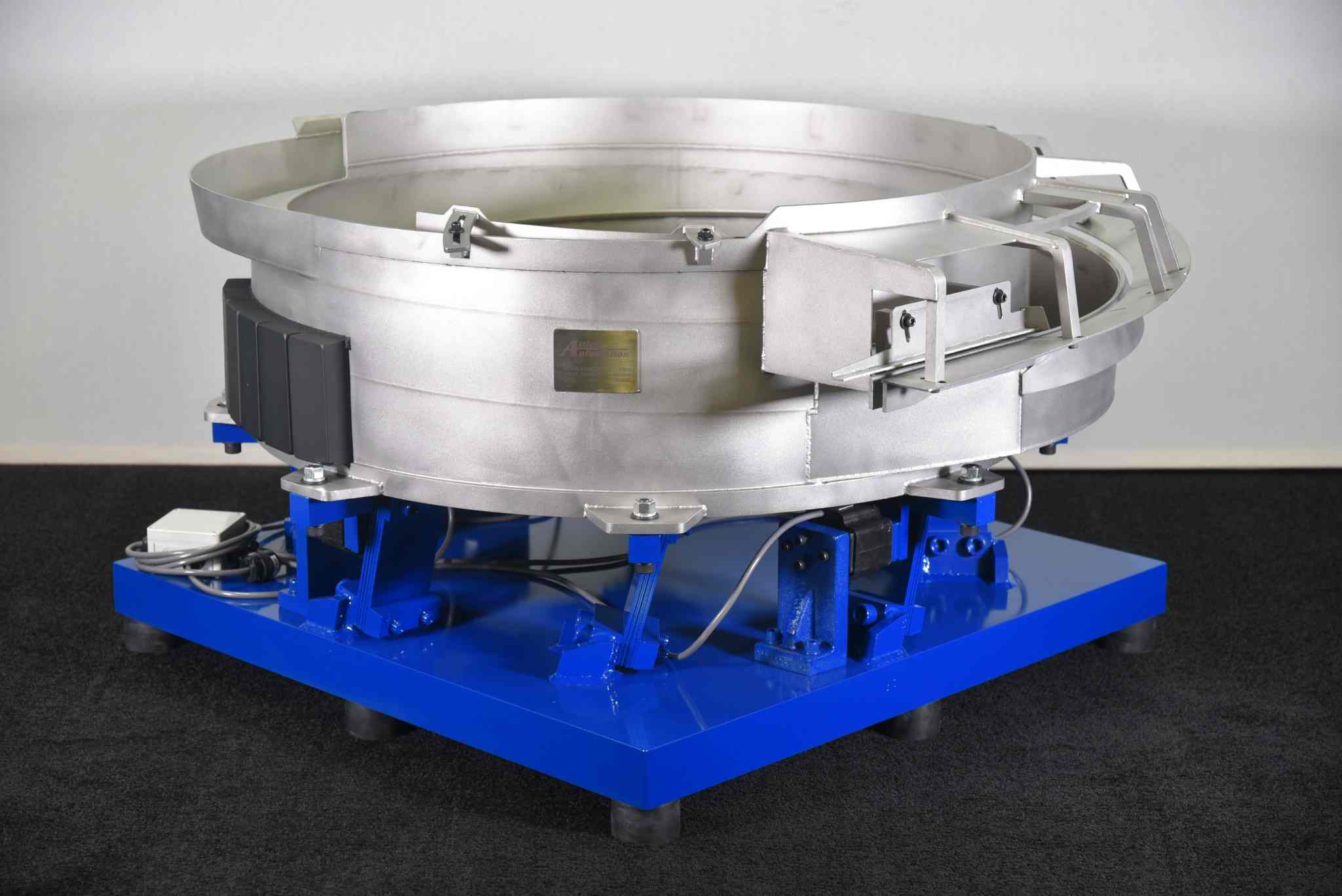
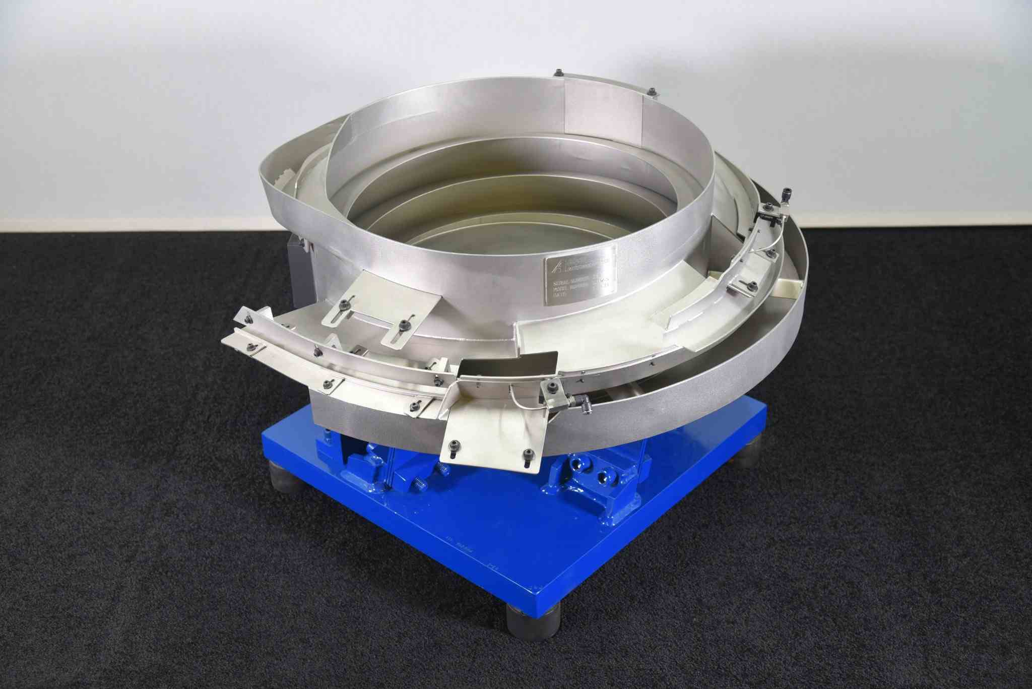
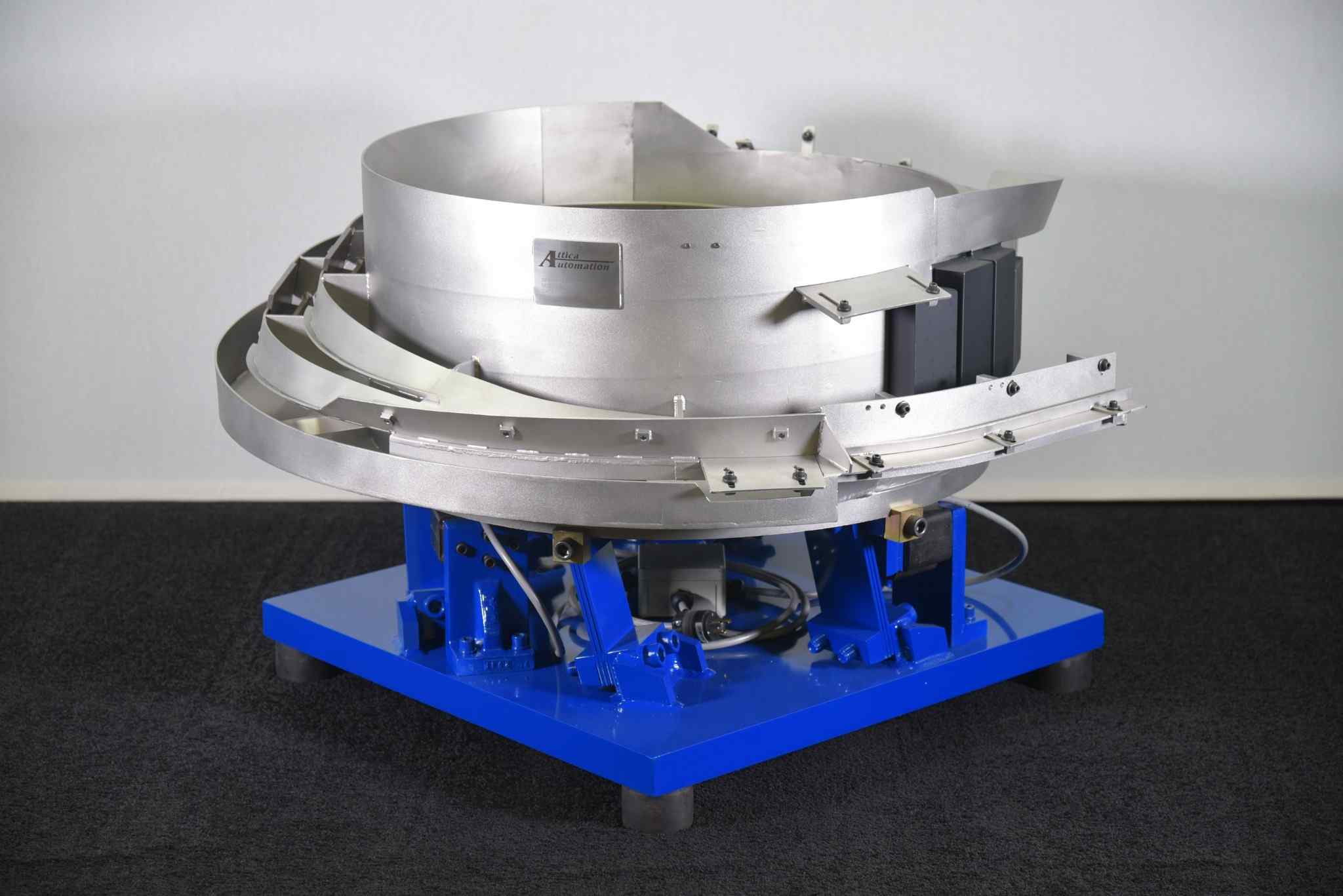
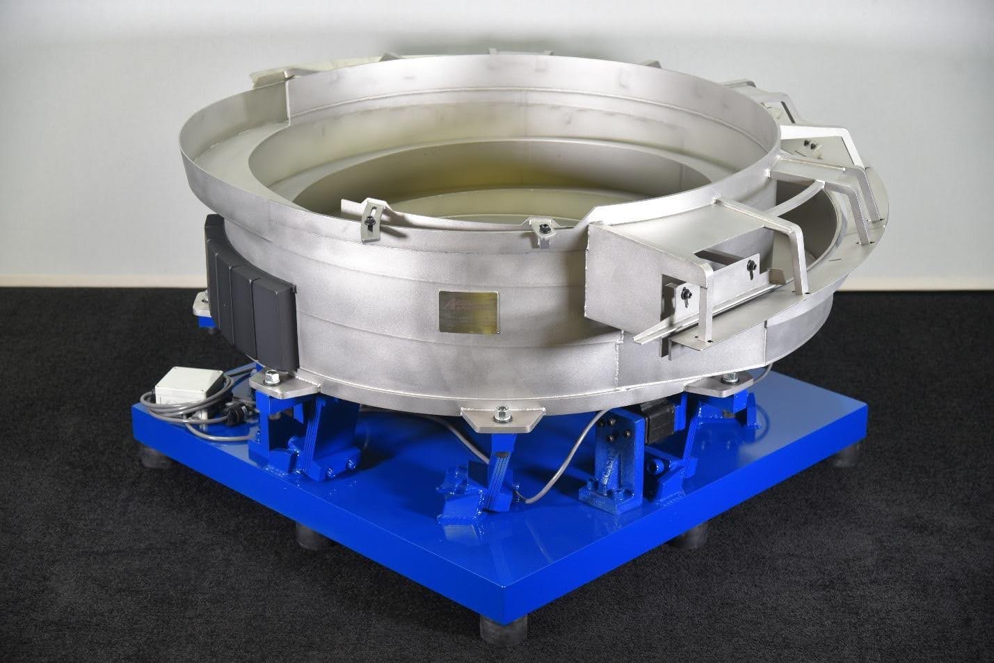
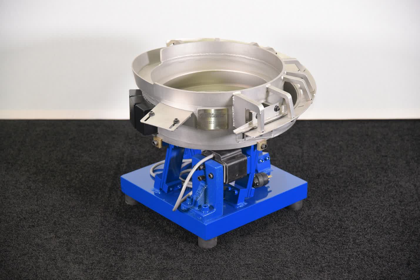
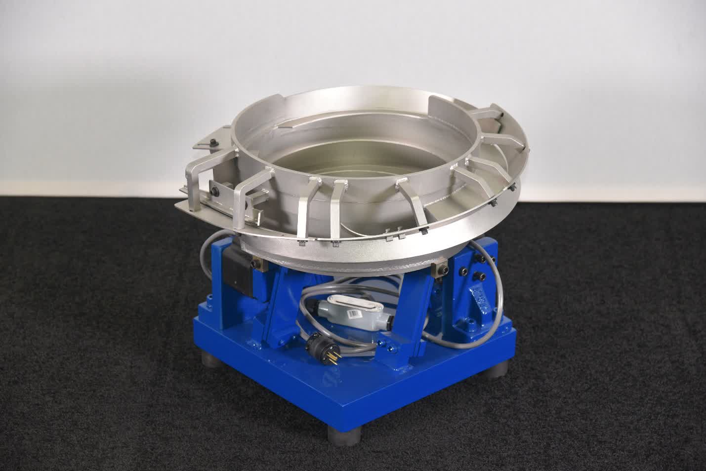
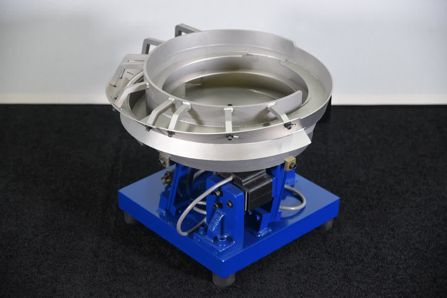
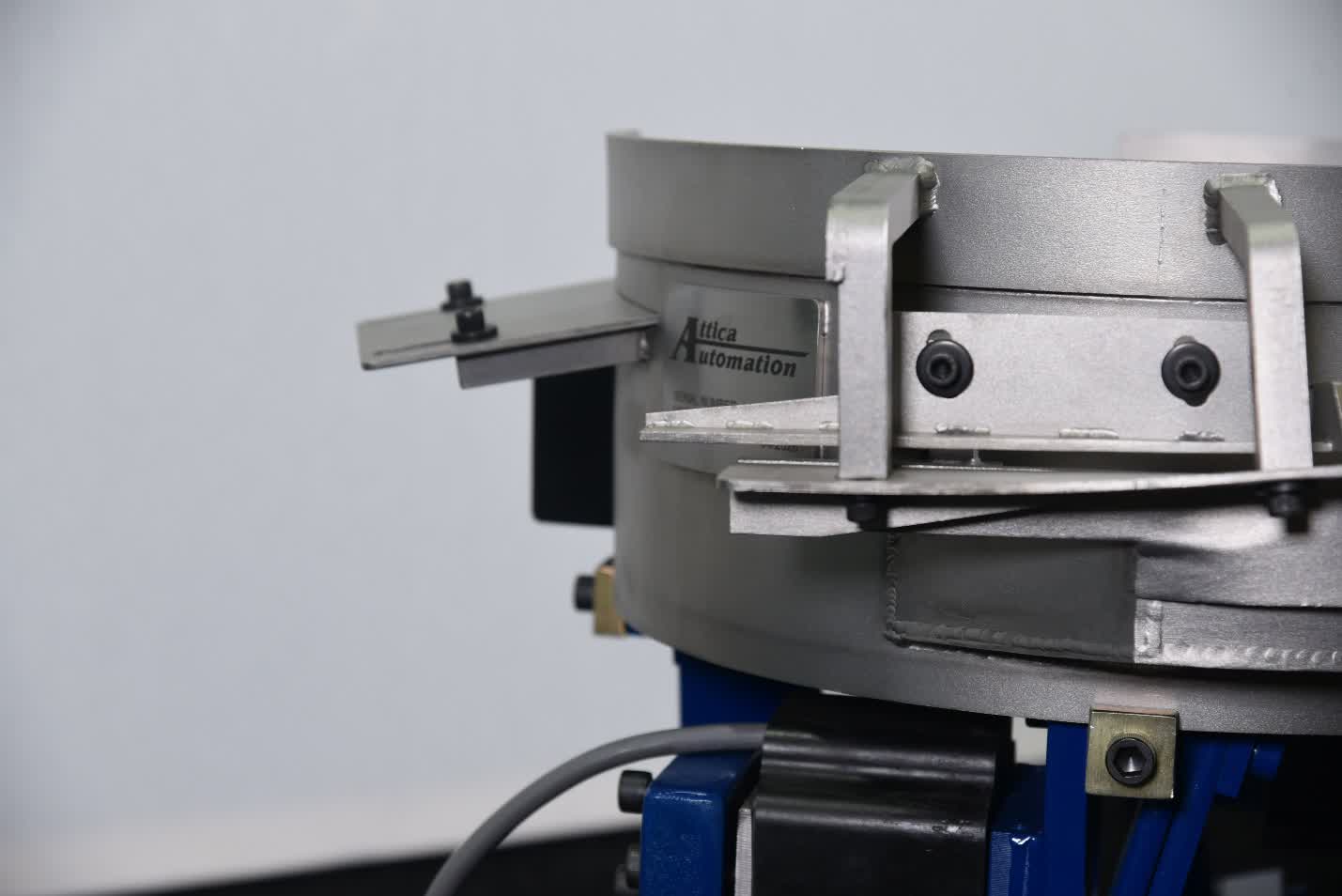
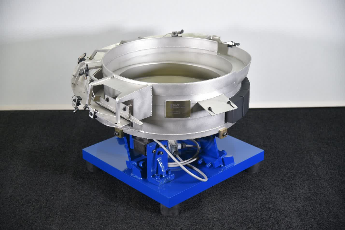
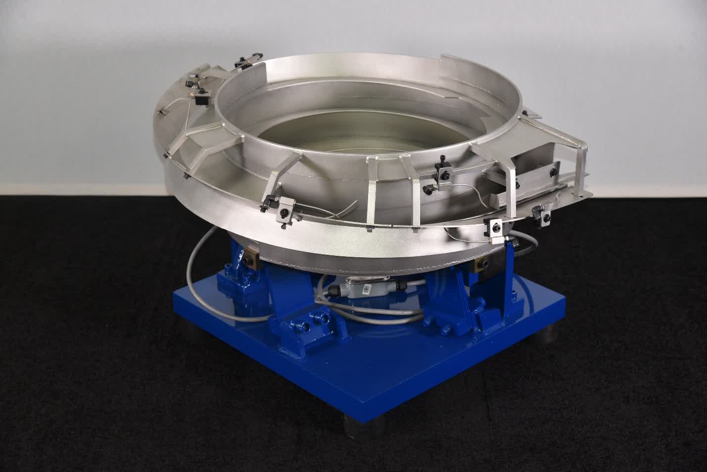
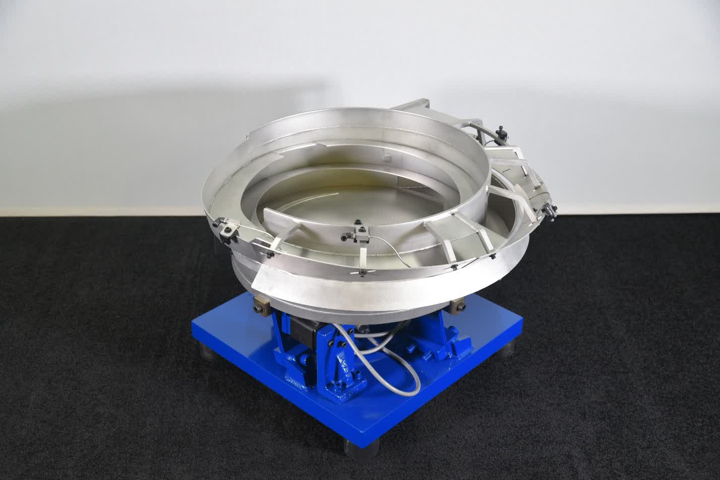
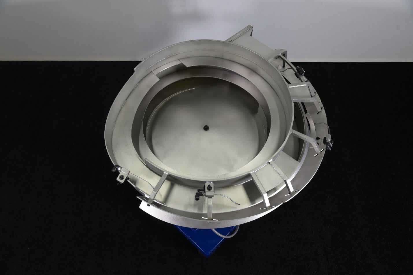
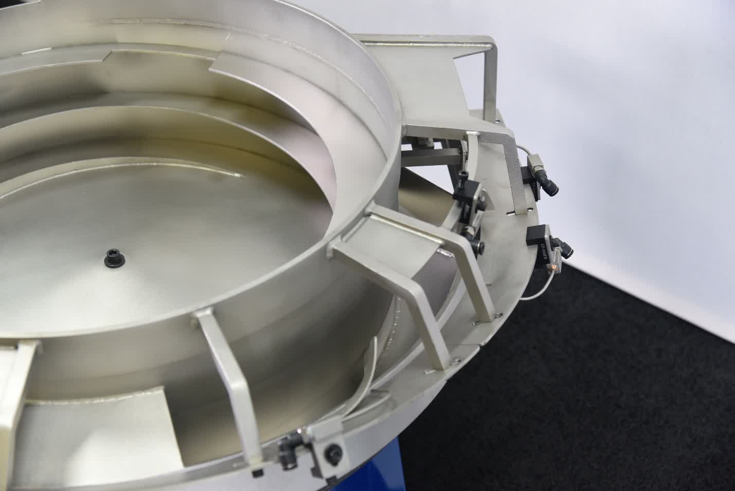
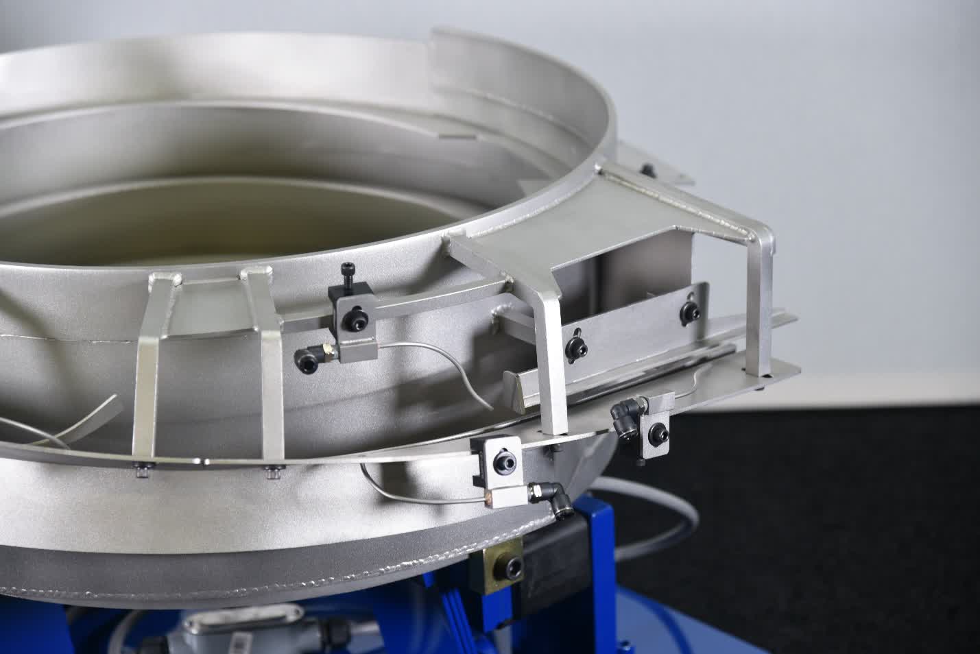
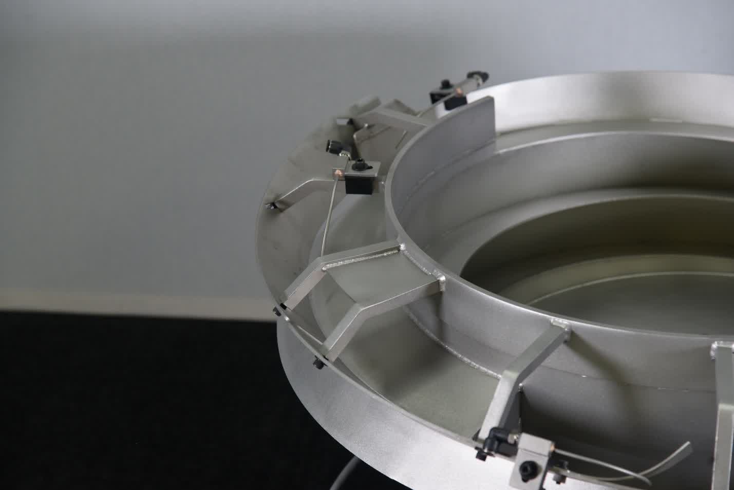
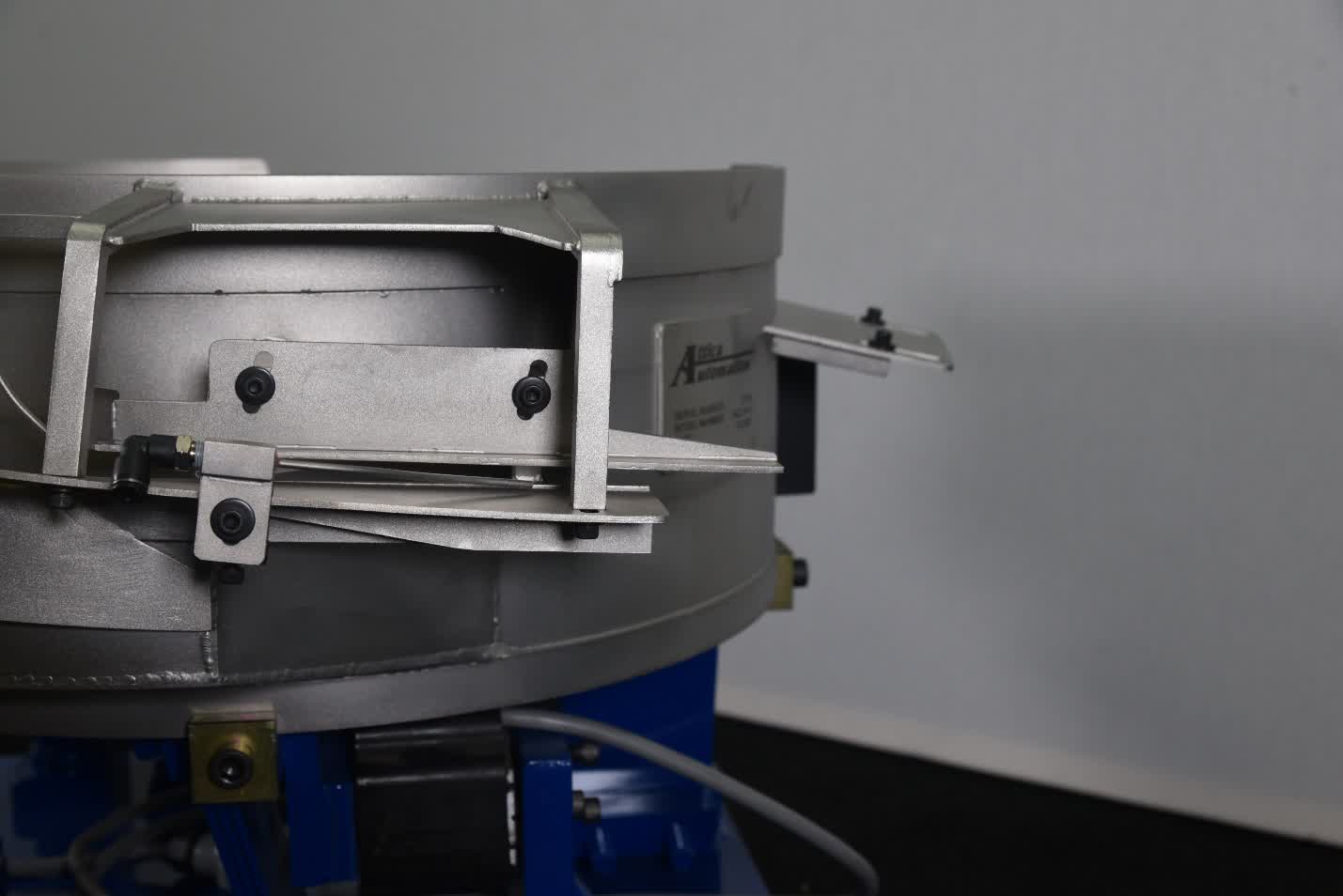
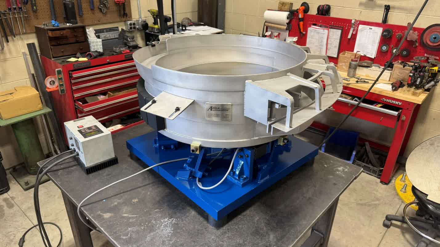
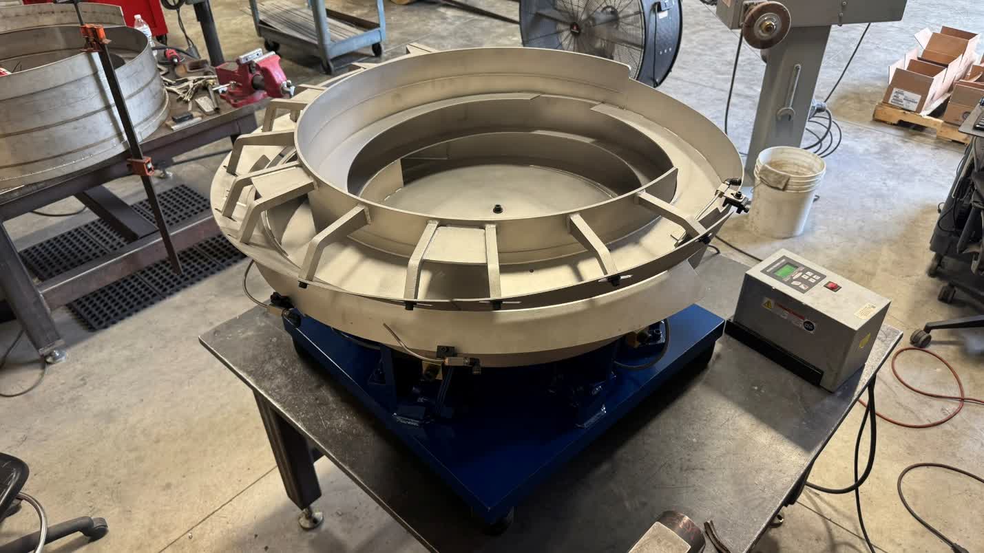
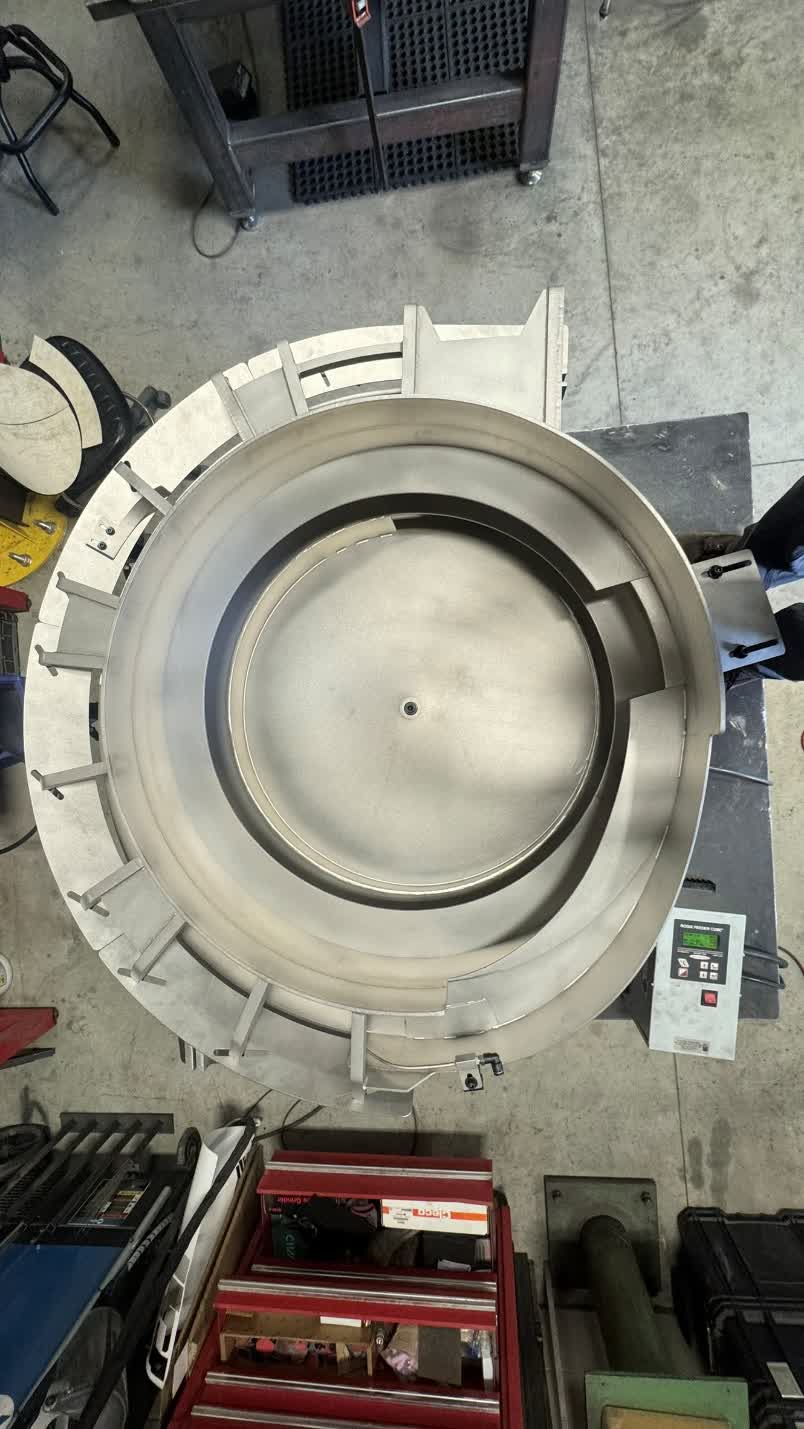
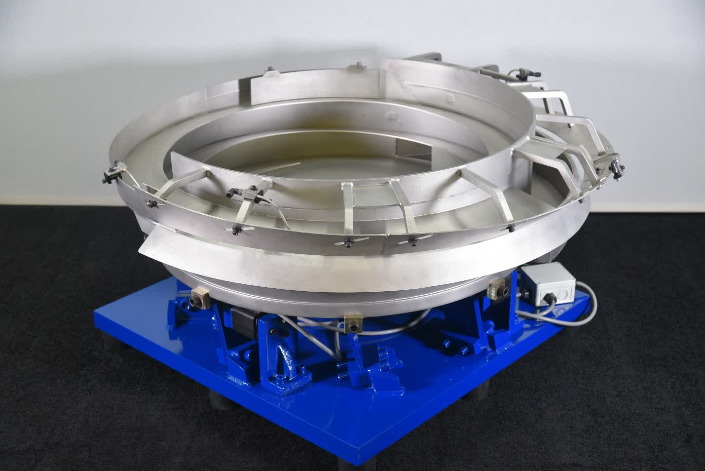
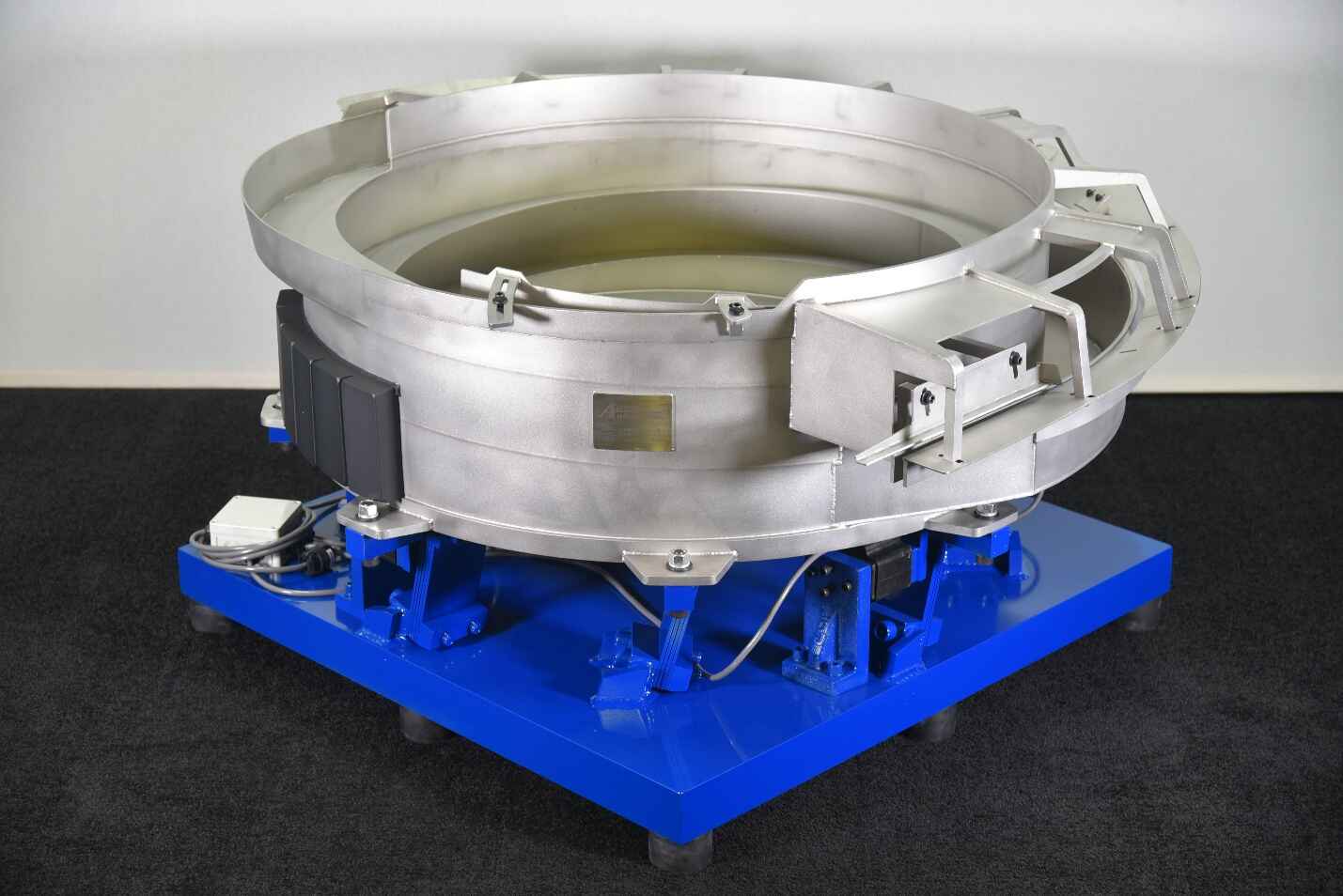
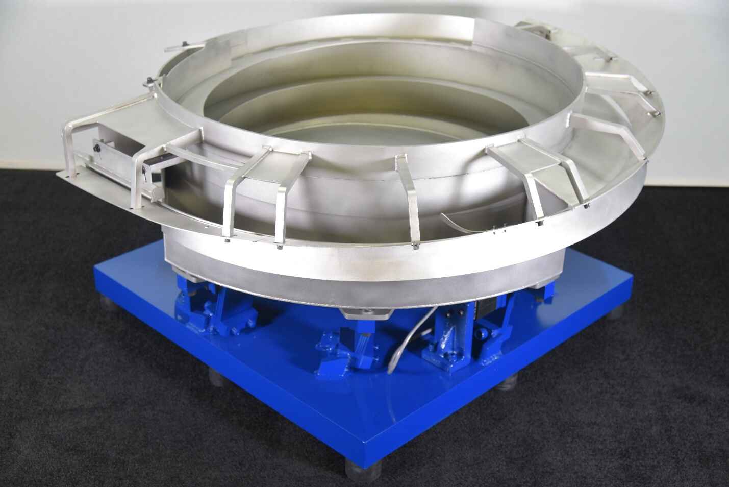
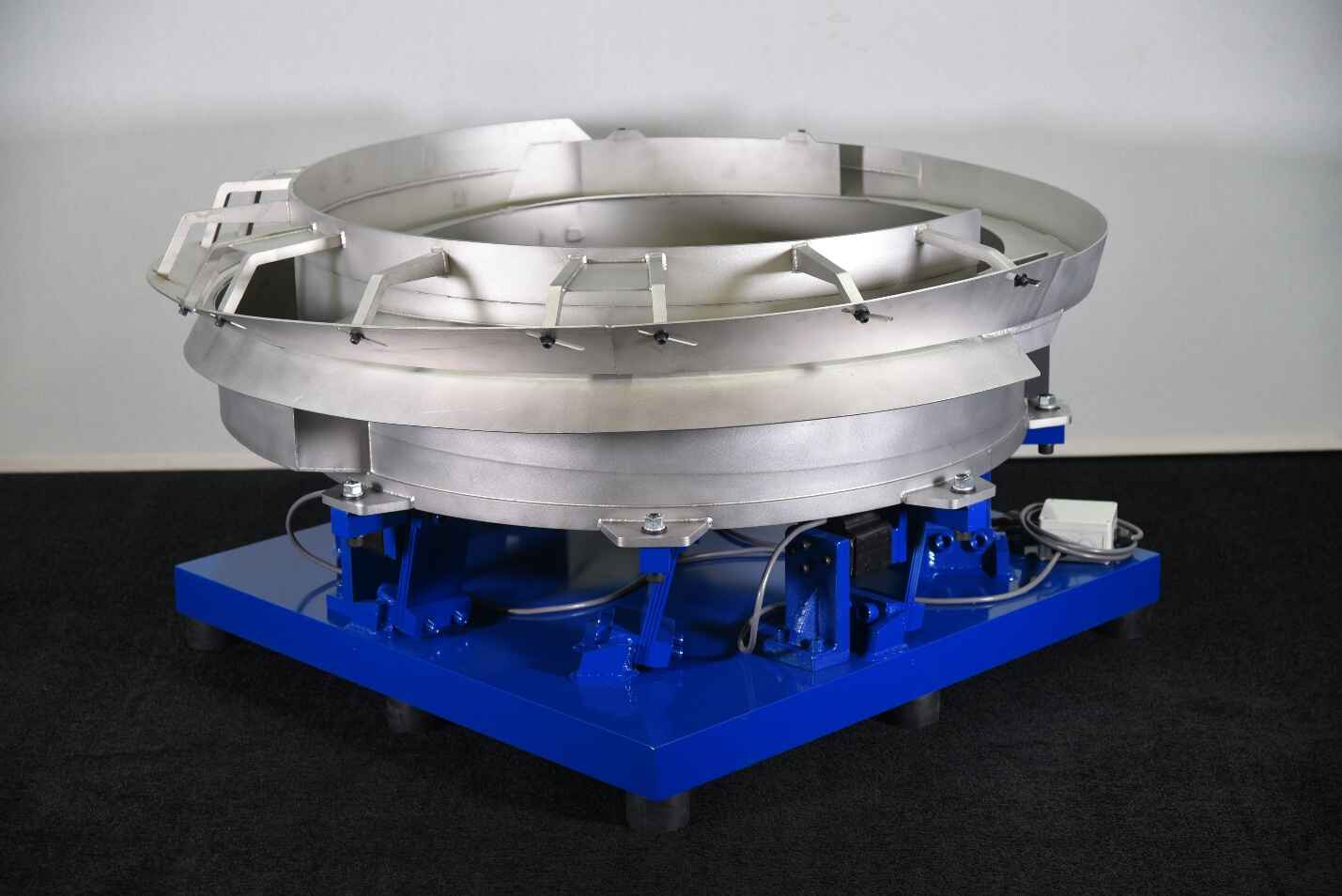
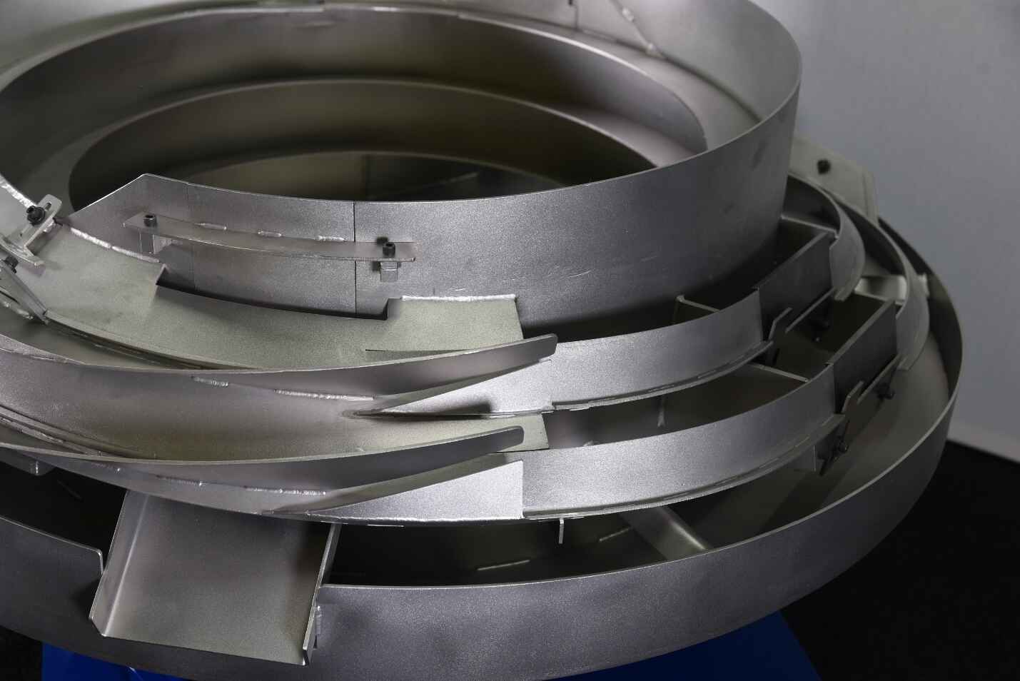
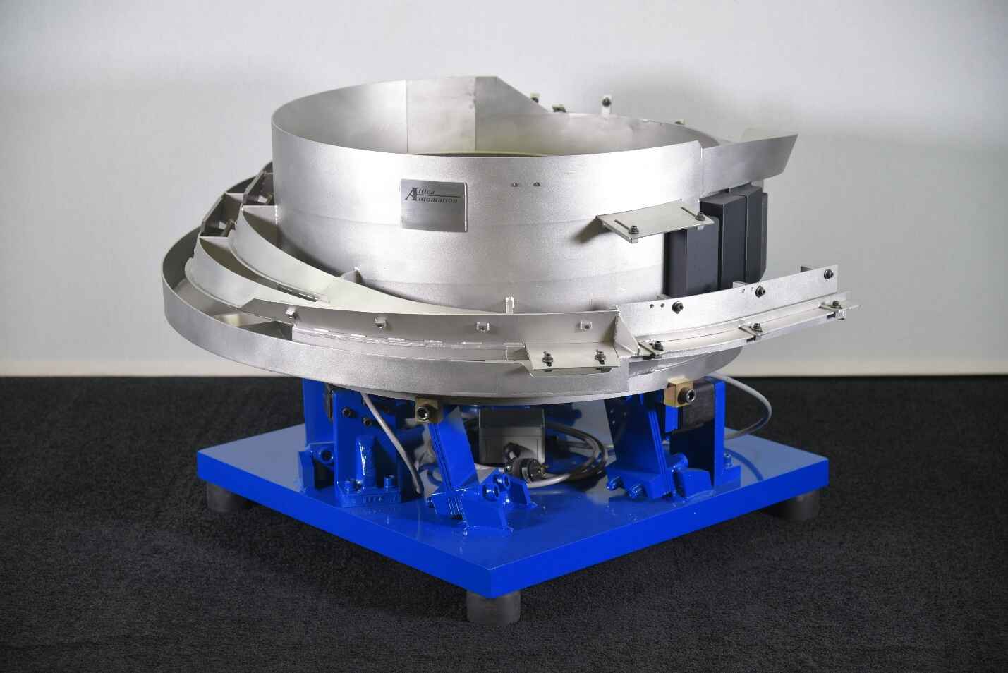
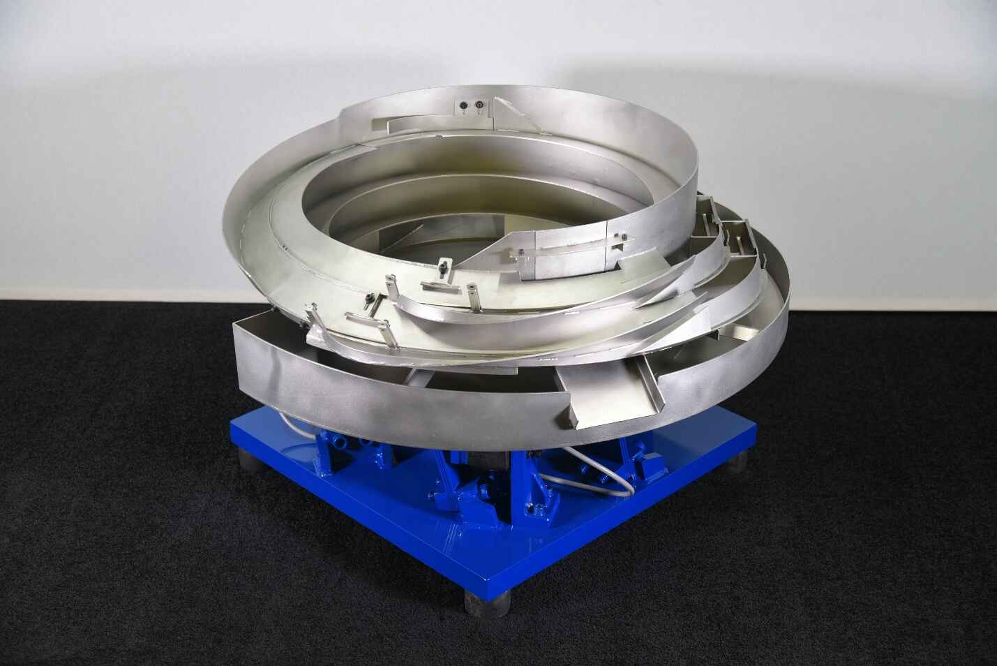
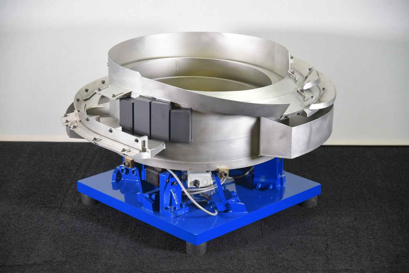
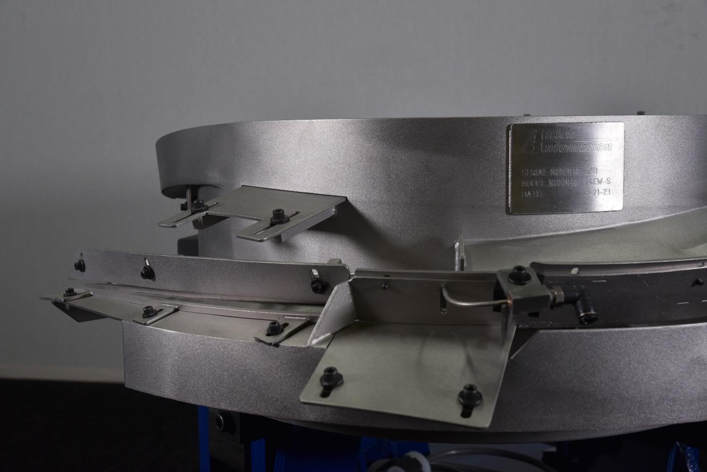
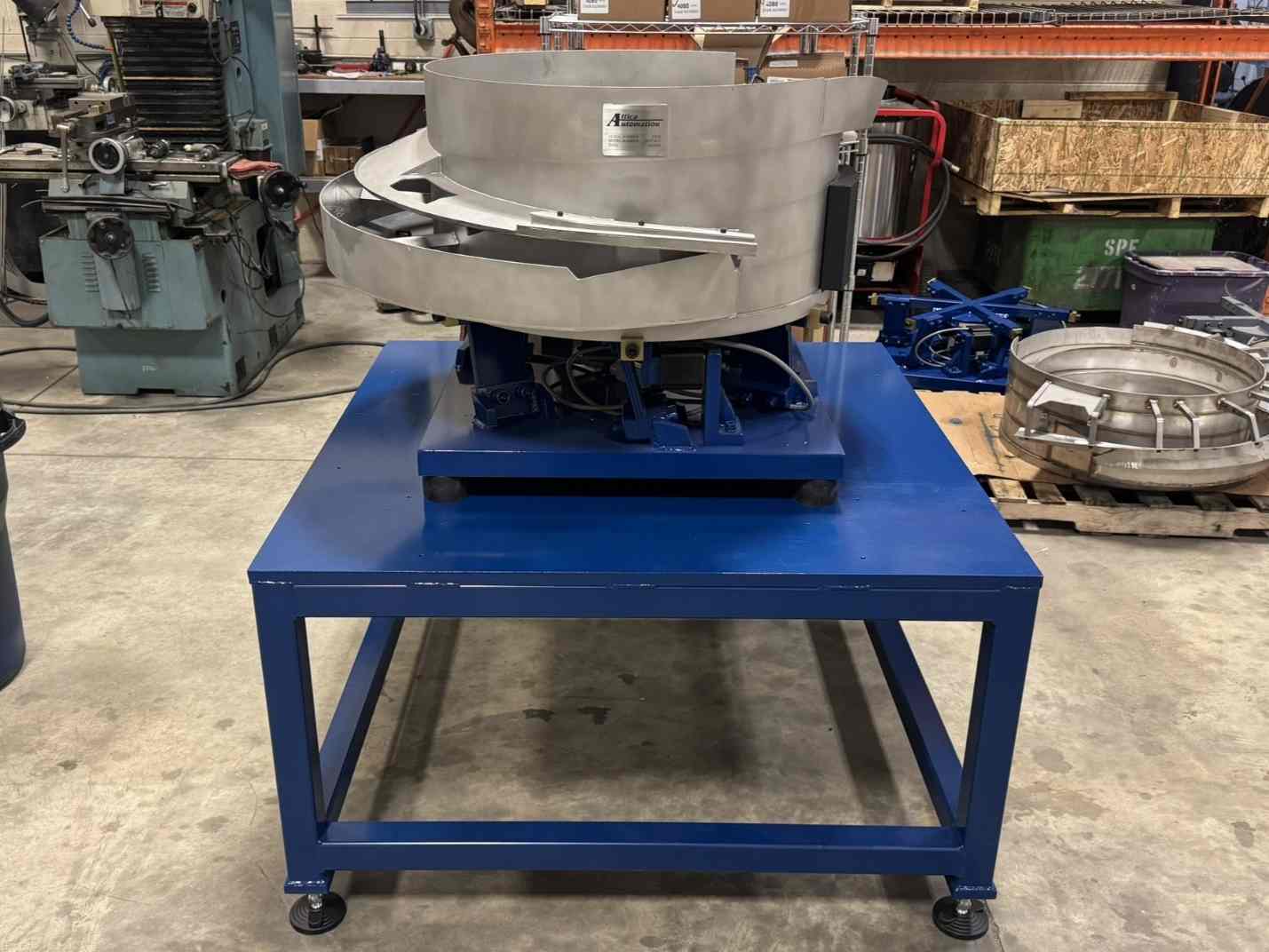
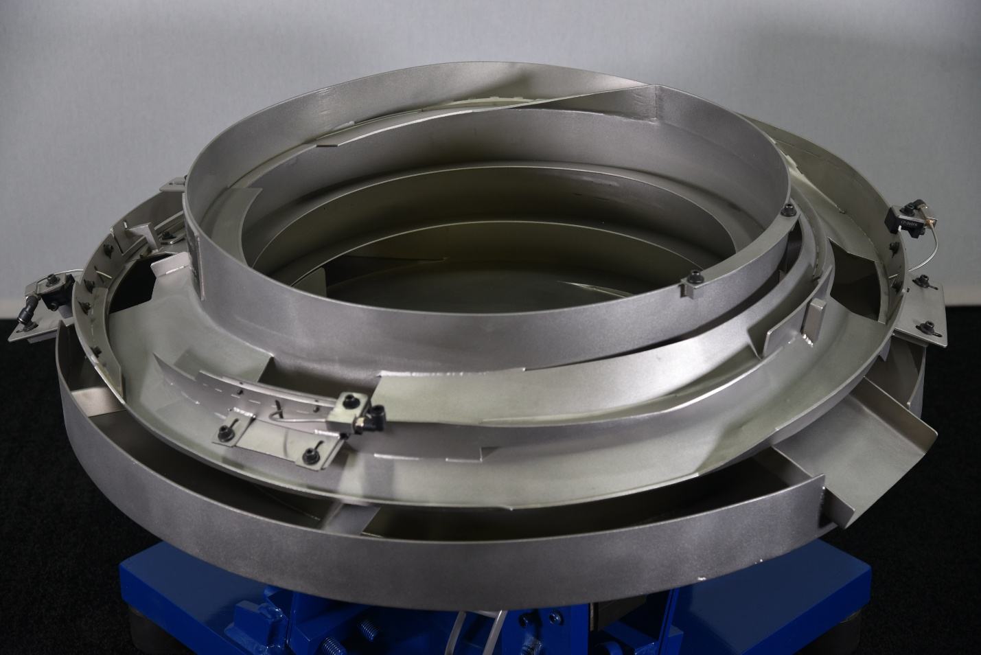
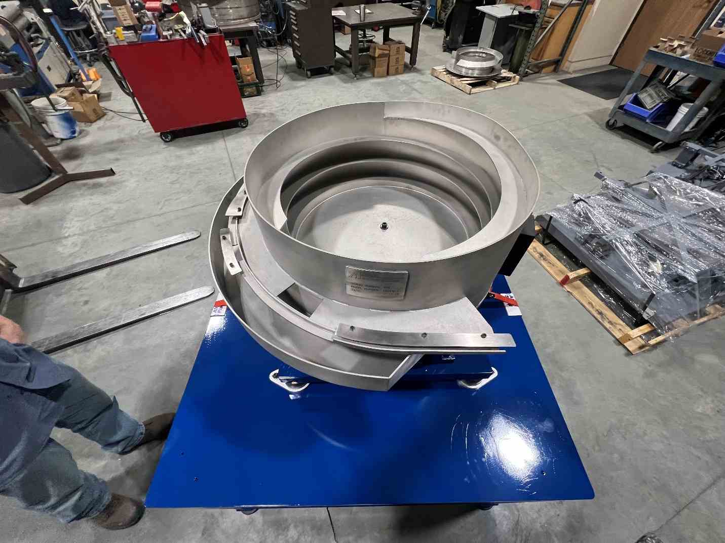
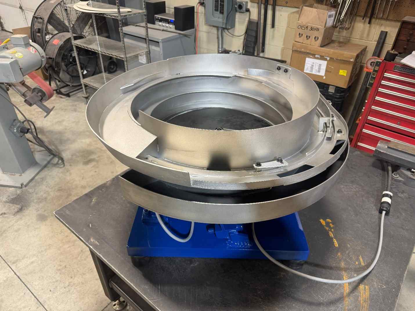
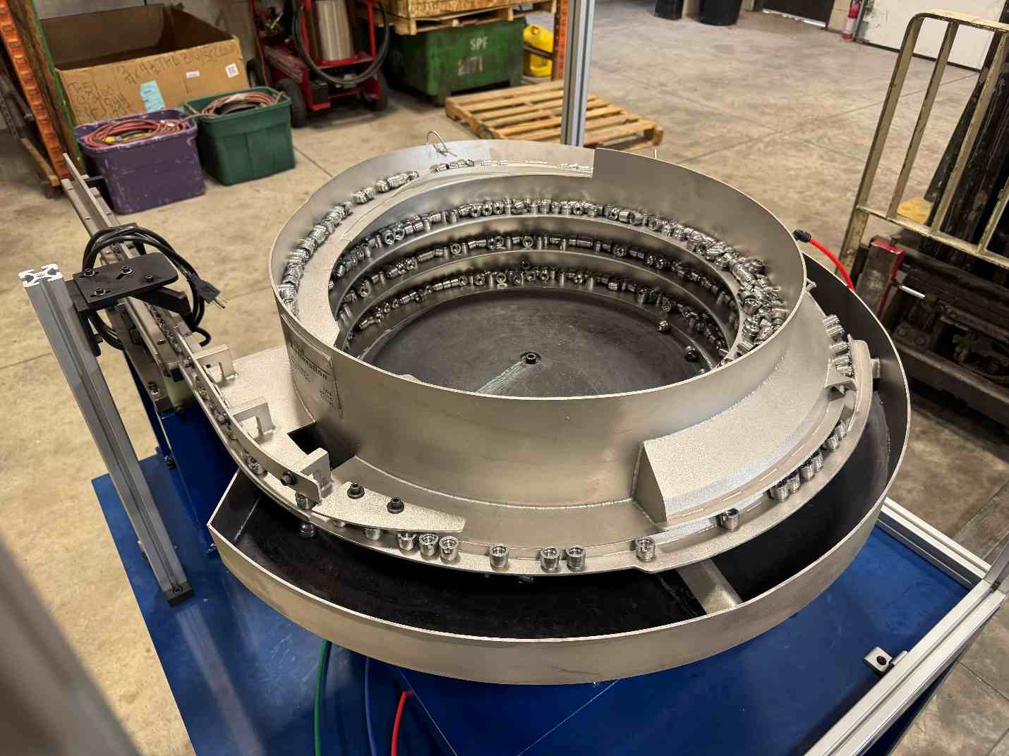
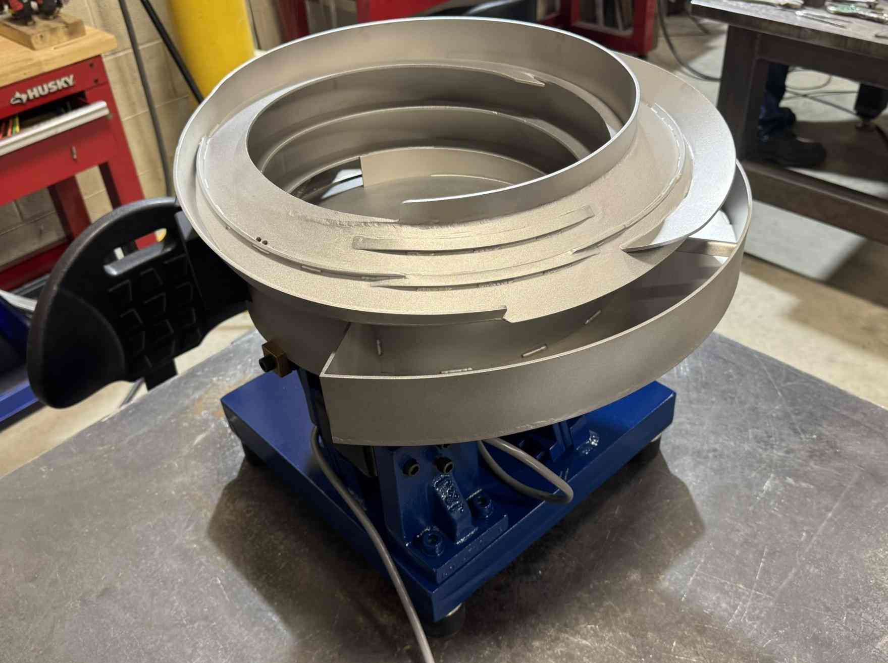
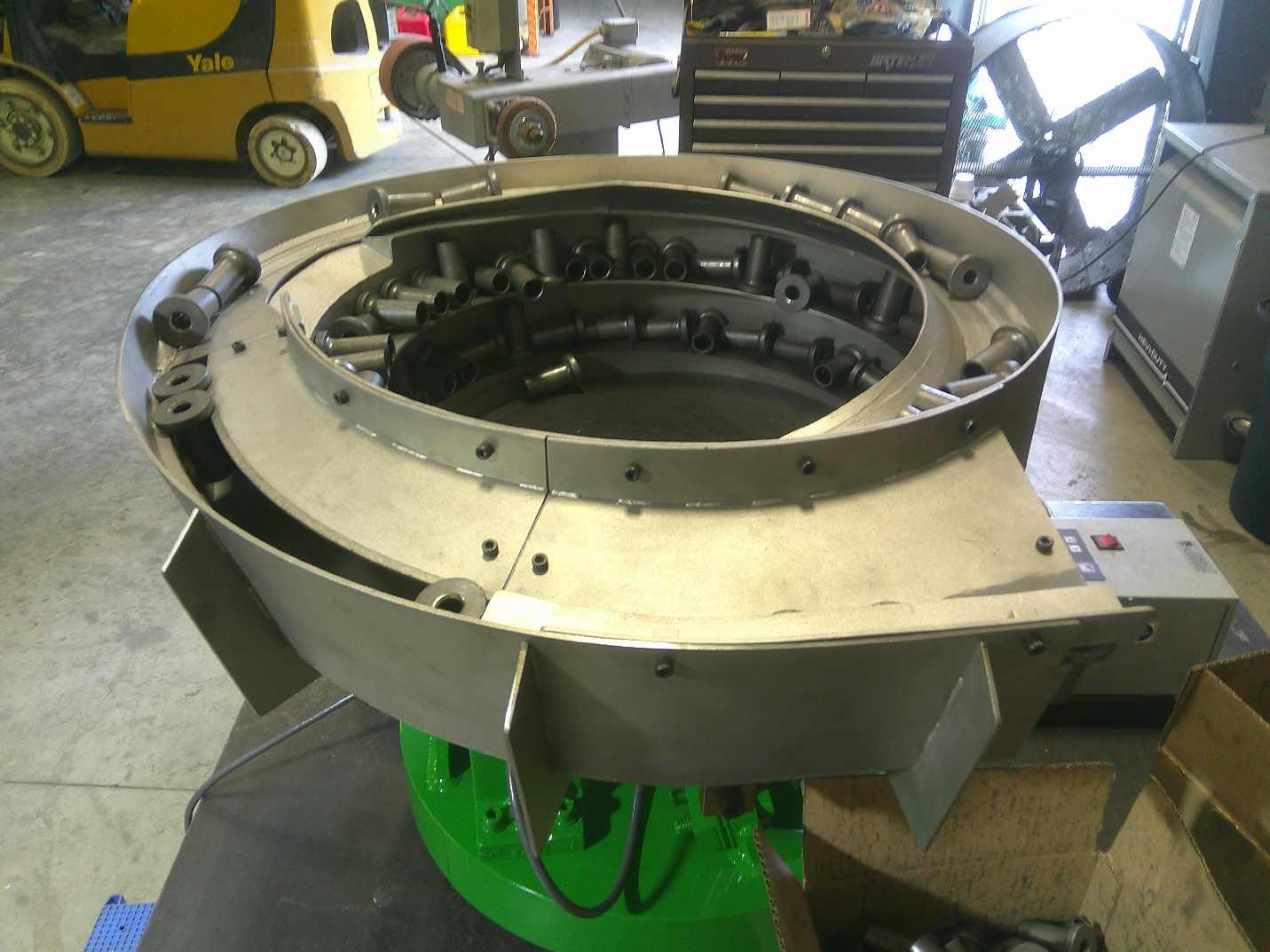
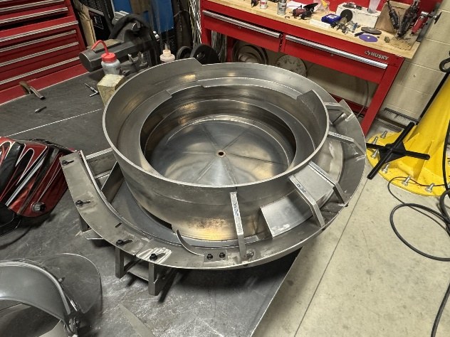
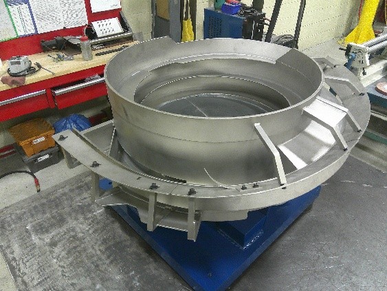
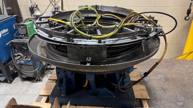
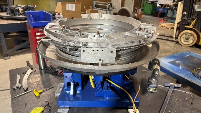
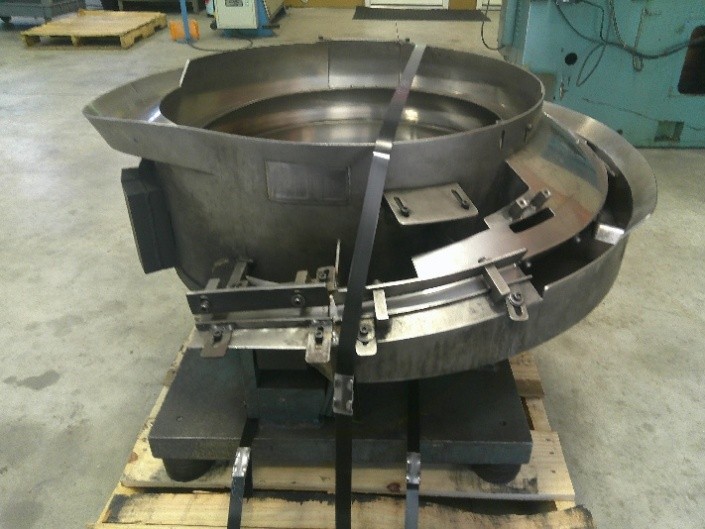
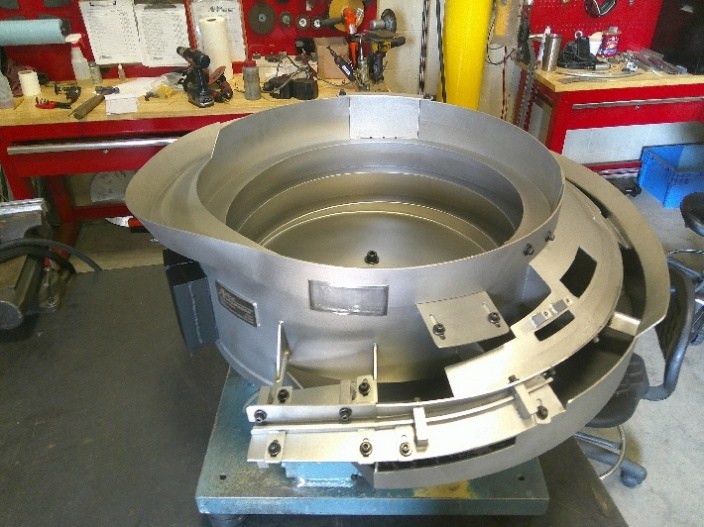
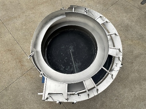
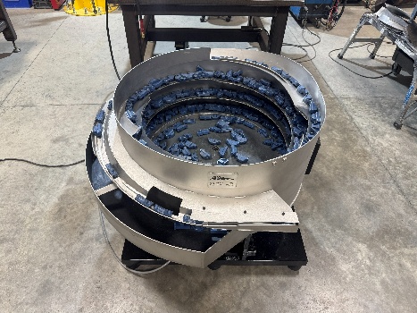
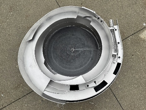
Attica Automation designs and builds vibratory
feeder systems for reliable, repeatable part
feeding and orientation.
Our feeder bowls can be configured for a wide
range of part geometries, feed rates, and
orientation requirements. Systems are available
as complete new builds, custom applications, or
retooled existing feeders.
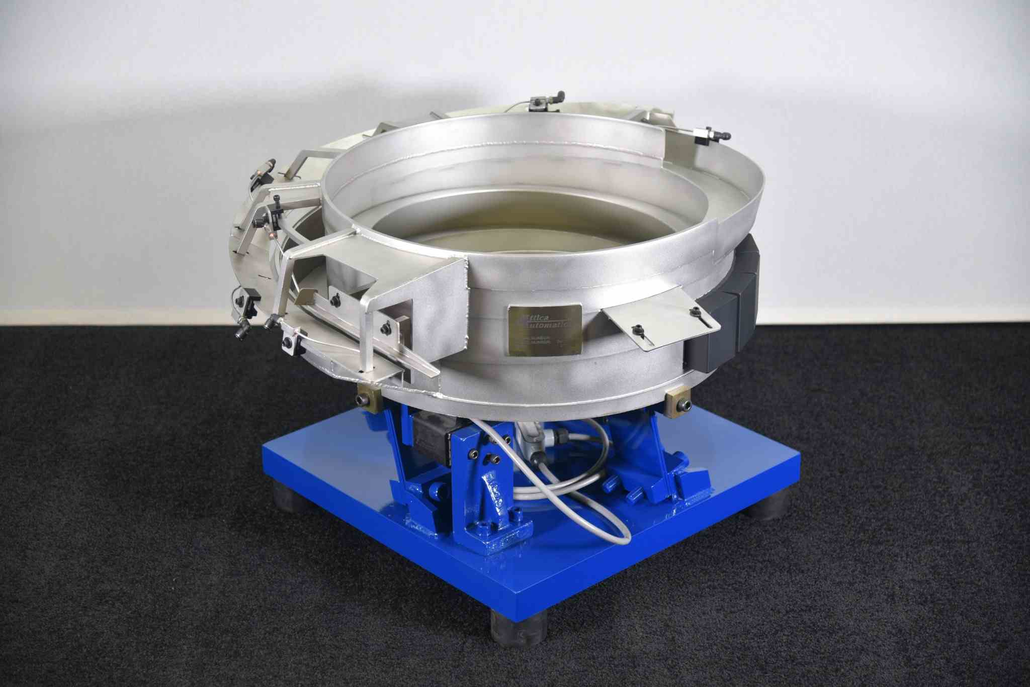
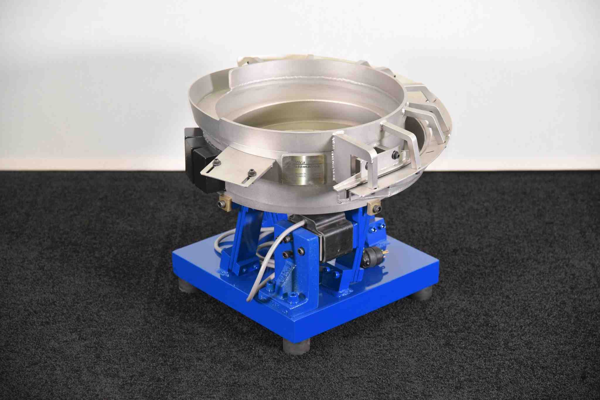
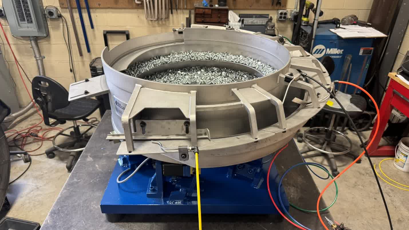
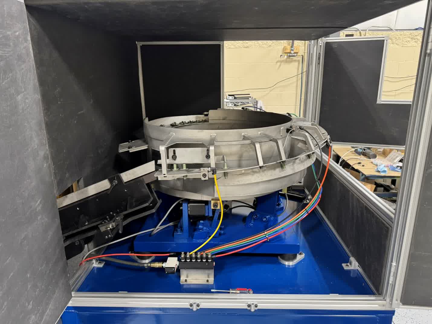
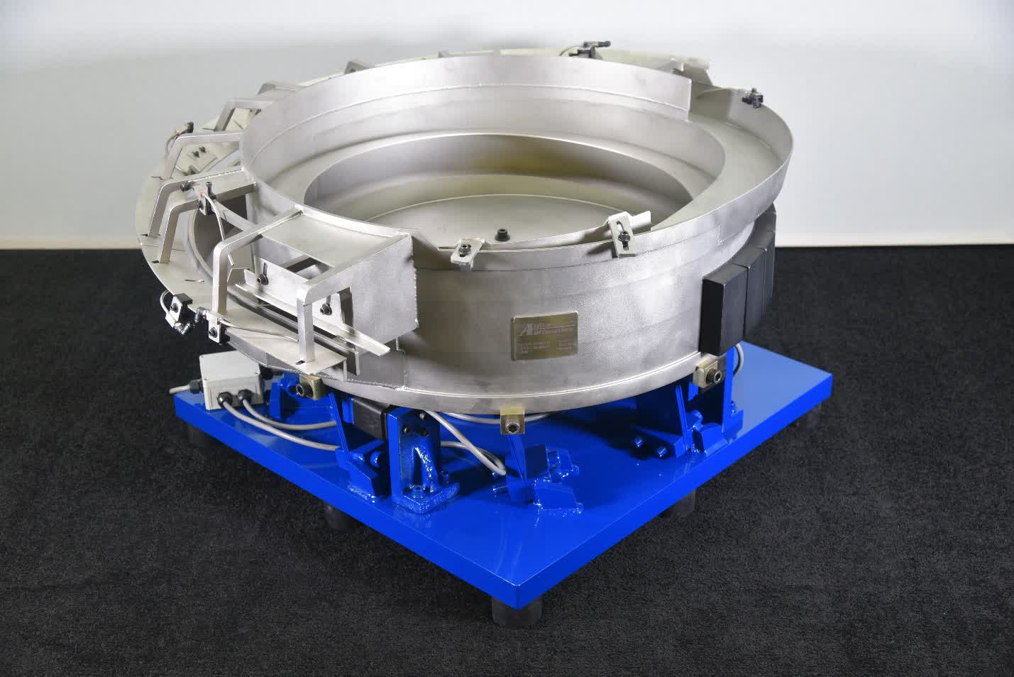
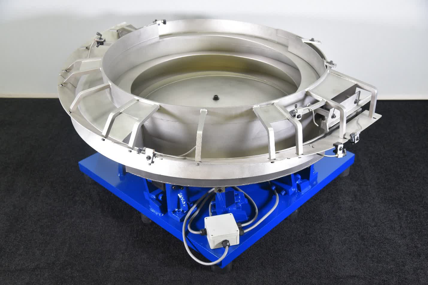
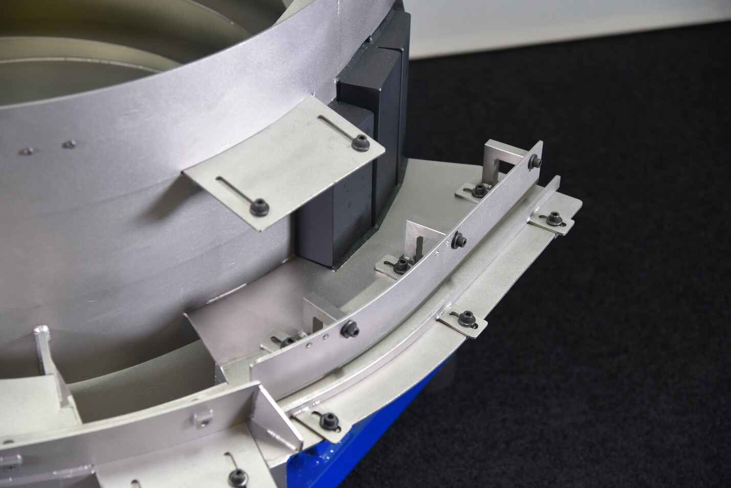
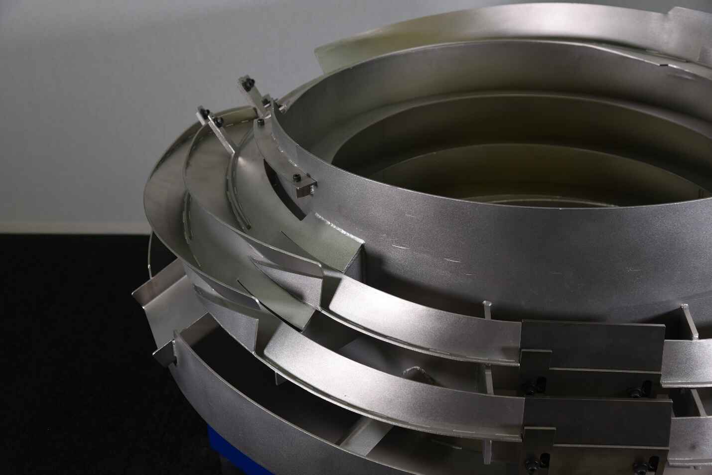
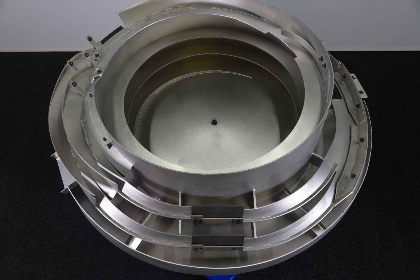
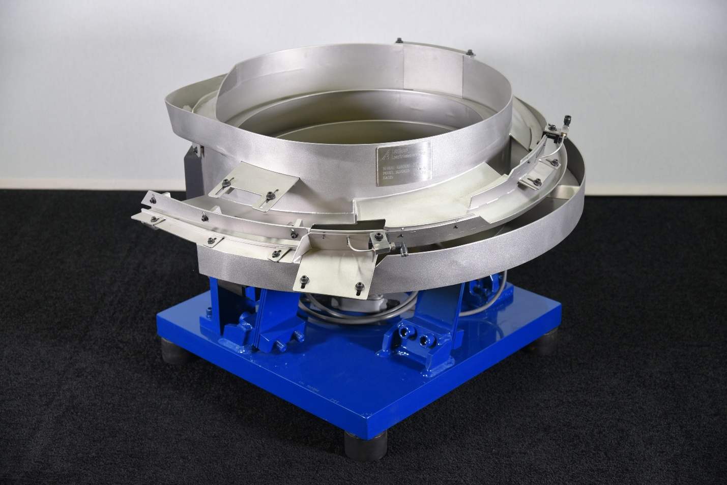
Vibratory Feeder Bowls are automated part-feeding
systems designed to separate, orient, and deliver bulk
parts in a consistent position to downstream equipment.
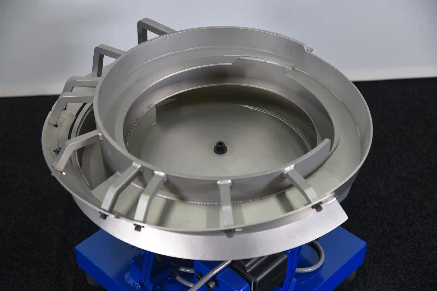
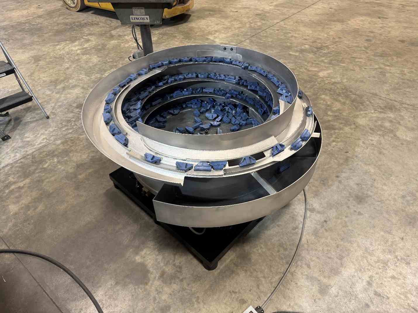
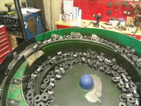
Parts are placed into the feeder bowl in bulk. Through
controlled vibration and custom tooling, the parts
travel around the bowl where they are sorted and
oriented before being discharged in the correct
position.
Typical Parts
Screws
Bolts
Studs
Washers
Pins
Rivets
Stampings
Plastic Components
Machined Components
Custom Parts
Benefits of Vibratory Feeder Bowls
Consistent Part Orientation
High Feed Rates
Reduced Manual Part Handling
Improved Production Efficiency
Repeatable Part Delivery
Continuous Automatic Feeding
Integration With Existing Automation
Custom Tooling for Difficult Part Geometries
Reduced Operator Involvement
Reliable Feeding for High-Volume Production
Each feeder system is designed around the specific part,
required orientation, desired feed rate, and downstream
equipment. Feed rate and performance depend on the
complete part geometry, weight, center of gravity,
surface condition, required orientation, and downstream
equipment.
Built for Industrial Production
Quality Feeder Bowl Construction
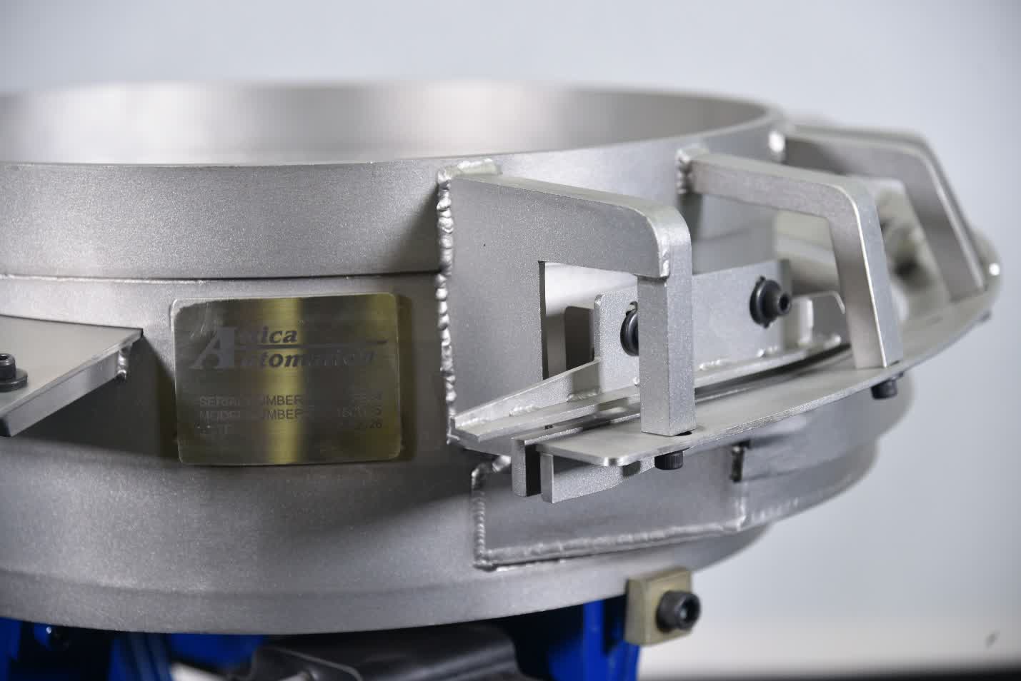
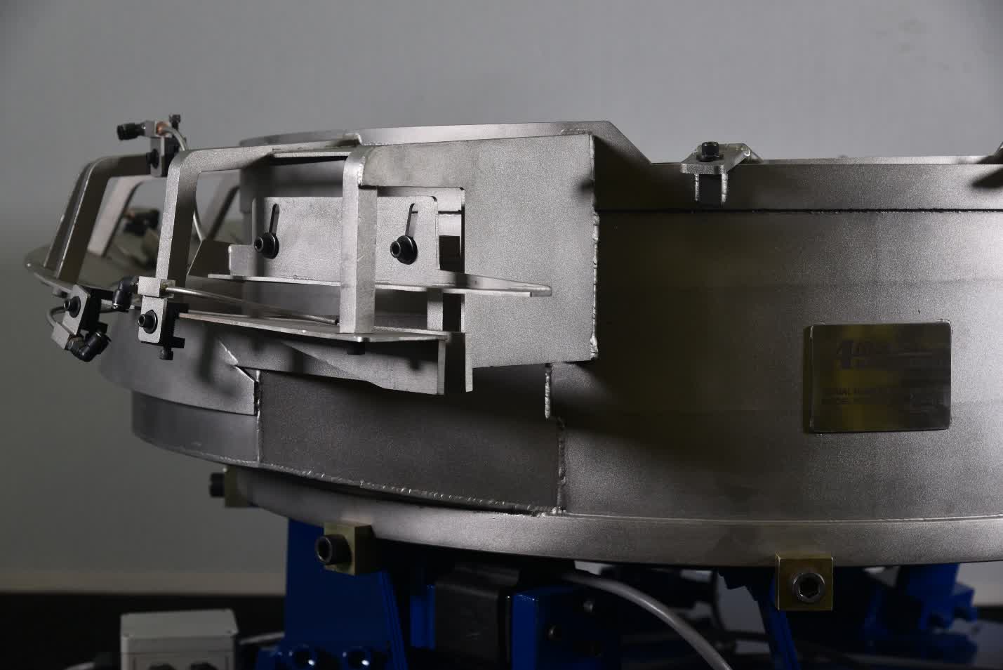
Attica Automation feeder bowls are constructed for
long-term use in demanding production environments. Our
feeder bowls are manufactured using
11 GA 300-Series Stainless Steel to
provide a strong, durable bowl structure with excellent
resistance to corrosion and everyday industrial use.
Standard Construction
11 GA 300-Series Stainless Steel Bowl
Construction
Heavy-Duty Welded Construction
Custom Fabricated Orientation Tooling
Reinforced Tooling Where Required
Designed for Continuous Industrial Operation
Application-Specific Construction Based on
Part Requirements
Hardened Steel High-Wear Components
Areas that experience increased part contact,
abrasion, or wear can be constructed from or
reinforced with hardened steel.
High-Wear Tooling Areas
Part Contact Surfaces
Discharge Tooling
Selectors
Rails and Guides
Orientation Features
Other High-Wear Locations
Built Around the Application
Material selection, tooling construction, wear surfaces,
and feeder configuration are determined by the specific
application. Part material, weight, geometry, production
rate, orientation requirements, and expected wear are
all considered when designing the feeder.
Quality construction, application-specific tooling, and
attractive lead times help make Attica Automation feeder
systems a practical solution for both new equipment and
existing production lines. Our goal is to build a feeder
that not only feeds the part correctly, but is
constructed to withstand the demands of the production
environment.
High-Speed Feeding for Headed, Flanged & Shanked
Parts
Screw Feeder Bowls
Screw Feeder Bowls are designed for parts with a defined
head, flange, shoulder, or similar feature with a shank
extending from it.
Typical parts include: Screws, bolts,
studs, rivets, pins, threaded fasteners, flanged
components, double-ended fasteners, and similar
headed-and-shank components.
Available Screw Feeder Bowl Sizes: 15"
| 24" | 30" | 36" | 42" Available in Clockwise and Counter-Clockwise
Rotation
For parts with simple geometry and favorable feeding
characteristics, feed rates can reach
800+ Parts/Minute. Screw Feeder Bowls
are not limited to simple parts. Custom tooling and
orientation features can be incorporated to accommodate
difficult part geometries, challenging centers of
gravity, and more complex orientation requirements.
Attica Screw Feeder Design Advantage
Open Tooling, Full Shank Support & Fast Part
Changeovers
Designed for higher feed rates, better part control,
fewer jams, and fast adjustment between part sizes.
Developed from 50 years of bowl-building
experience.
Attica Automation’s screw feeder design was
developed by our senior bowl builder, drawing on 50
years of experience building and refining vibratory
feeder bowls for demanding production applications.
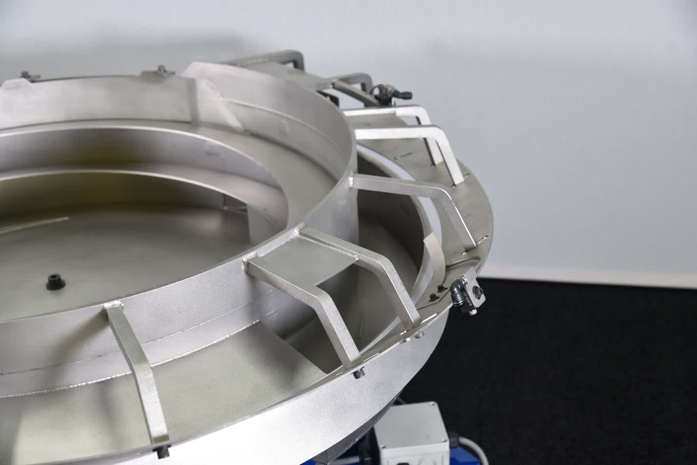
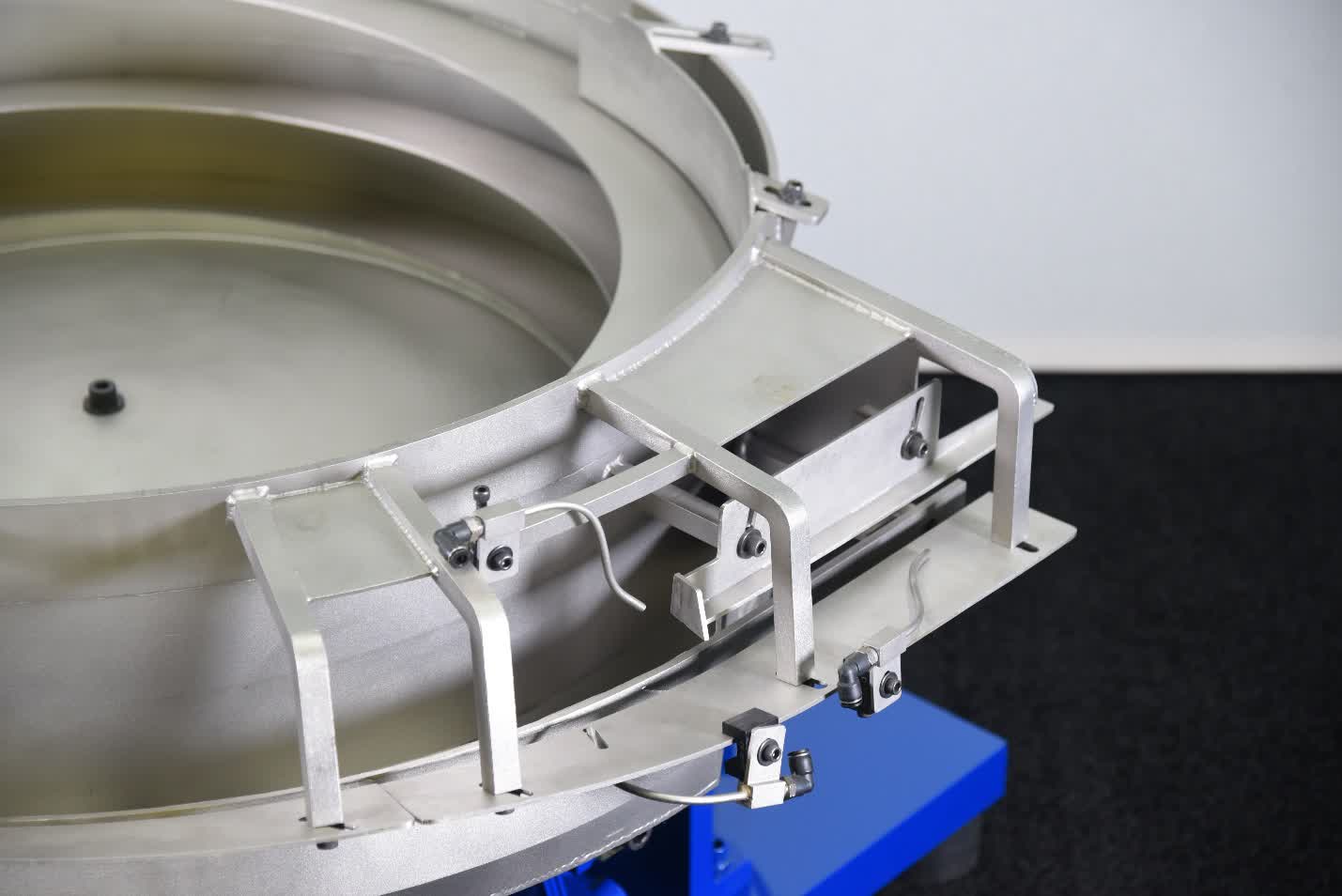
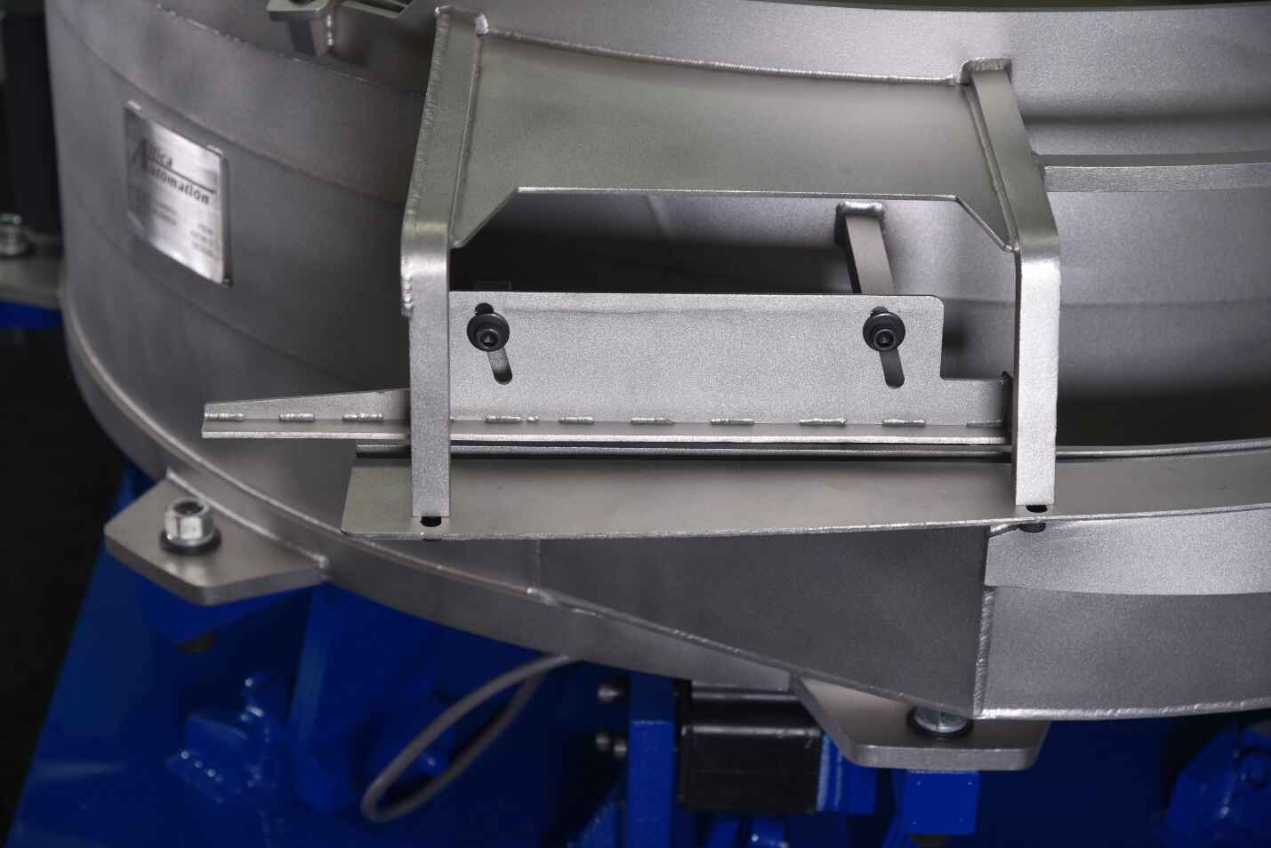
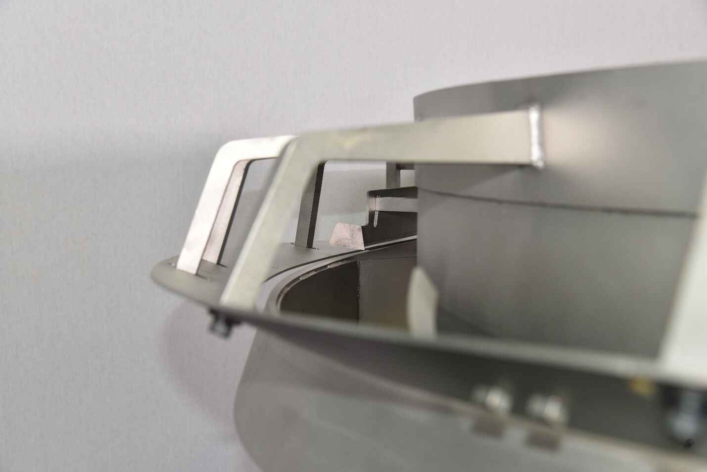
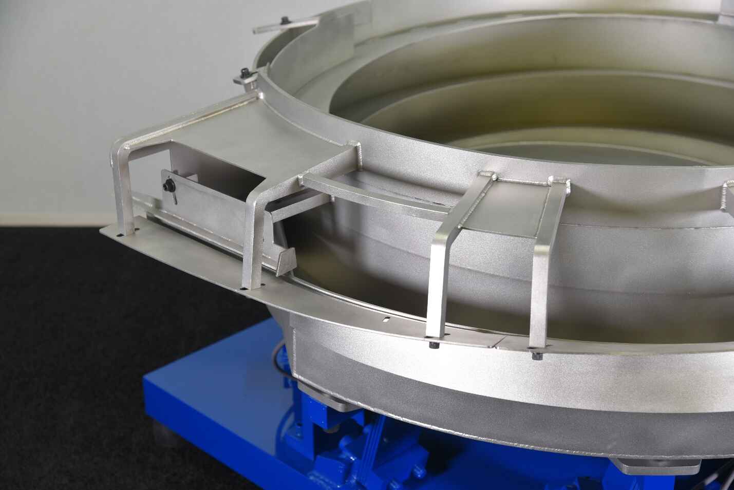
Attica Automation screw feeders use an
open tooling design that provides
easy visual access to the feeding and orientation
tooling from virtually any direction. This makes the
feeder easier to inspect, adjust, troubleshoot, and
modify without unnecessarily obstructing access to
the tooling.
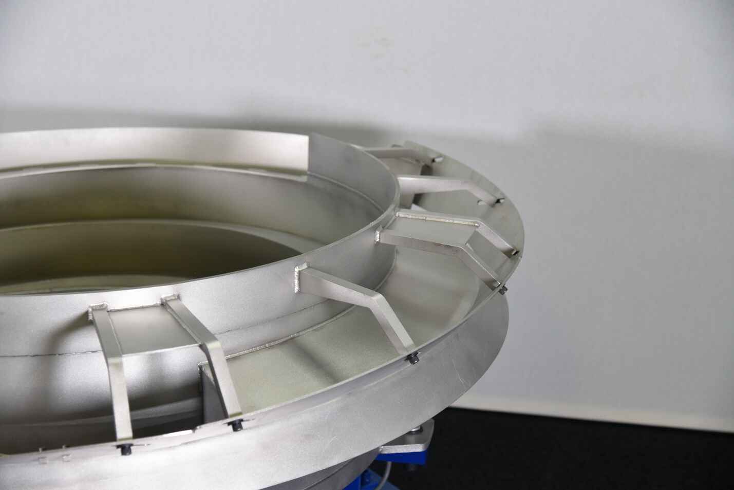
Our design keeps the
part shank supported all the way to the
discharge, providing better control of the part throughout
the feeding process and helping eliminate
criss-cross jams that can occur
when parts lose support or overlap.
Open Tooling Design — Easy
visual and physical access to tooling from
virtually any direction.
Shank Supported to Discharge —
Maintains control of the part through the full
feed path and helps eliminate criss-cross jams.
Higher Feed Rates — Our screw
feeder design has been proven in production
applications to outperform other designs with
higher achievable feed rates.
Less Jamming — Improved part
control helps reduce interruptions and maintain
consistent feeding.
Fast Part-Size Adjustments —
Adjustments for a part change can typically be
completed in only a couple of minutes.
One Tool for All Adjustments —
Simplifies setup and reduces the time required
to make feeder adjustments.
Quick Application-Specific
Modifications
— The open design makes it faster and easier to
modify tooling for unique or difficult parts.
Designed for fast setup and production:
The combination of open access, continuous shank
support, simple adjustment points, and one-tool
adjustment helps reduce setup time while improving
feeding consistency and overall performance.
▶
42" Feeder Bowl Running Parts
Video placeholder from content document.
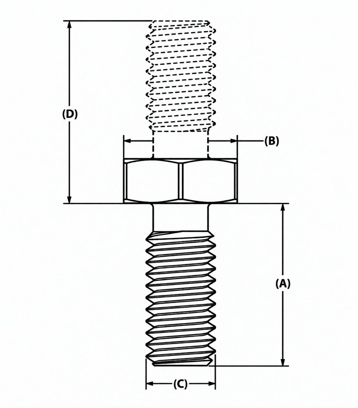
Screw Feeder Part Dimensions
Use the drawing letters below:
(A) Shank Length
(B) Head / Flange Diameter
(C) Shank Diameter
(D) Double-Ended Extension
Above Head
15" Screw Feeder Bowl
CW / CCW Available
15" Screw Feeder Bowl
▶
15" Bowl Running Parts
Part Specification
Inch
Metric
(A) Maximum Shank Length
3"
76.2 mm
(B) Maximum Head / Flange
Diameter
1"
25.4 mm
(C) Maximum Shank Diameter
.25"
6.35 mm
(D) Maximum Double-Ended
Extension Above Head
1.75"
44.45 mm
Potential Feed Rate – Simple Geometry:
900+ PPM
24" Screw Feeder Bowl
CW / CCW Available
24" Screw Feeder Bowl
▶
24" Bowl Running Parts
Part Specification
Inch
Metric
(A) Maximum Shank Length
4"
101.6 mm
(B) Maximum Head / Flange
Diameter
2"
50.8 mm
(C) Maximum Shank Diameter
.625"
15.875 mm
(D) Maximum Double-Ended
Extension Above Head
2.5"
63.5 mm
Potential Feed Rate – Simple Geometry:
900+ PPM
30" Screw Feeder Bowl
CW / CCW Available
30" Screw Feeder Bowl
▶
30" Bowl Running Parts
Part Specification
Inch
Metric
(A) Maximum Shank Length
6"
152.4 mm
(B) Maximum Head / Flange
Diameter
2.25"
57.15 mm
(C) Maximum Shank Diameter
.75"
19.05 mm
(D) Maximum Double-Ended
Extension Above Head
2.75"
69.85 mm
Potential Feed Rate – Simple Geometry:
600+ PPM
36" Screw Feeder Bowl
CW / CCW Available
36" Screw Feeder Bowl
▶
36" Bowl Running Parts
Part Specification
Inch
Metric
(A) Maximum Shank Length
8"
203.2 mm
(B) Maximum Head / Flange
Diameter
2.25"
57.15 mm
(C) Maximum Shank Diameter
.875"
22.225 mm
(D) Maximum Double-Ended
Extension Above Head
3"
76.2 mm
Potential Feed Rate – Simple Geometry:
600+ PPM
42" Screw Feeder Bowl
CW / CCW Available
42" Screw Feeder Bowl
▶
42" Bowl Running Parts
Part Specification
Inch
Metric
(A) Maximum Part Length
10"
254 mm
(B) Maximum Head / Flange
Diameter
2.25"
57.15 mm
(C) Maximum Shank Diameter
1"
25.4 mm
(D) Maximum Double-Ended
Extension Above Head
3.5"
88.9 mm
Potential Feed Rate – Simple Geometry:
600+ PPM
Typical Part Capacity: These values are
intended as general application guidelines. Custom
tooling or modifications can be added when part geometry
or orientation requirements make standard feeding more
difficult.
High-Speed Feeding for Thin, Circular Parts
Washer Feeder Bowls
Washer Feeder Bowls are designed for parts with a thin,
circular or ring-shaped geometry.
Typical parts include: Flat washers,
spacers, retaining rings, thin circular stampings,
gaskets, seals, and similar round components.
Available Washer Feeder Bowl Sizes: 15"
| 24" | 30" Available in Clockwise and Counter-Clockwise
Rotation
For simple, consistently shaped parts, feed rates can
reach 800+ Parts/Minute. Washer Feeder
Bowls can also be modified with custom tooling and
orientation features for difficult part geometries or
parts that do not naturally feed in the required
orientation.
New Washer Feeder Innovation
Precision High-Speed Orientation for Beveled &
Crowned Washers
An innovative solution to achieve high feed rates of
properly oriented washers.
Attica Automation’s new washer feeder design
provides an innovative solution for applications
requiring
high feed rates with consistent washer
orientation.
The feeder can identify and orient washers based on
even
the smallest bevels, crowns, or subtle
differences between the two sides of the
washer. Custom orientation tooling uses these features to
ensure the washer is discharged in the correct
position, with the
beveled or crowned side consistently facing
up.
This allows manufacturers to maintain proper washer
orientation without sacrificing production speed.
High-Speed Washer Feeding
Consistent Bevel-Up or Crown-Up Orientation
Can Orient From Very Small Bevel Differences
Reliable Orientation of Similar-Looking Washer
Sides
Reduced Incorrectly Oriented Parts
Designed for High-Volume Production
Custom Tooling Based on the Specific Washer
Geometry
Precision Orientation at High Feed
Rates:
Even when the difference between the two sides of a
washer is minimal, the feeder can be tooled around
those small geometric features to provide reliable
orientation and repeatable delivery to downstream
equipment.
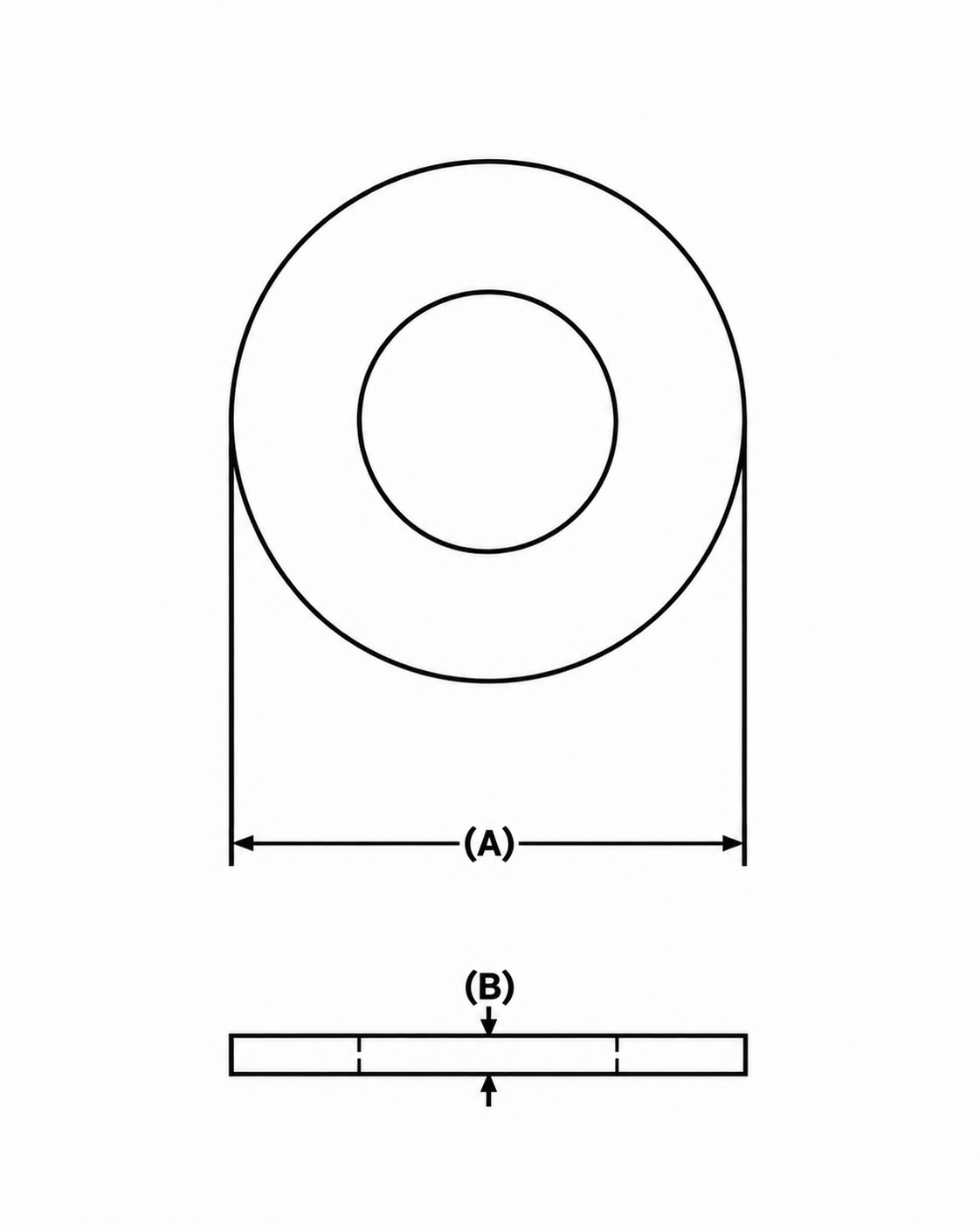
Washer Feeder Part Dimensions
Use the drawing letters below:
(A) Outside Diameter
(B) Thickness
15" Washer Feeder Bowl
Photo Slide To Add / Video To Add
15" Washer Feeder Bowl
Photo SlidePhotos to be added
here
15" Washer Feeder Bowl
▶
15" Washer Bowl Running Parts
Part Specification
Inch
Metric
(A) Maximum Outside Diameter
.75"
19.05 mm
(B) Maximum Thickness
.25"
6.35 mm
Potential Feed Rate – Simple Geometry:
800+ PPM
24" Washer Feeder Bowl
Photo Slide To Add / Video To Add
24" Washer Feeder Bowl
Photo SlidePhotos to be added
here
Typical Part Capacity: These values are
intended as general application guidelines. Custom
tooling can be added when part geometry or orientation
requirements make standard feeding more difficult.
Designed Around Your Part
Custom Feeder Bowls
When a standard Screw Feeder or Washer Feeder is not the
right solution, Attica Automation can design a Custom
Feeder around the specific part and production
requirements.
Every Custom Feeder is developed around the requirements
of the individual application rather than a
predetermined part-size range.
Custom Feeder Bowl Examples
▶
Custom Feeder Bowls Running
Video area requested in content document.
Flip, Bolt-In & Custom Orientation Tooling for
Difficult Parts
Custom Part Orientation Tooling
Custom Part Orientation Tooling is available for parts
that require additional control or orientation before
entering the final feeder tooling.
Custom Flip Tooling
Bolt-In Tooling
Head-Heavy Part Orientation
Part Flipping or Repositioning
Orientation of Double-Ended Parts
Controlled Transitions into Final Tooling
Custom Guides and Selectors
Application-Specific Orientation Features
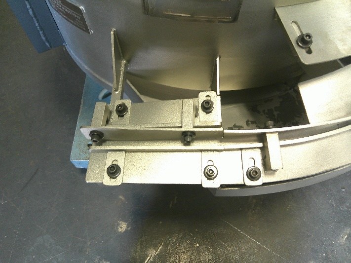
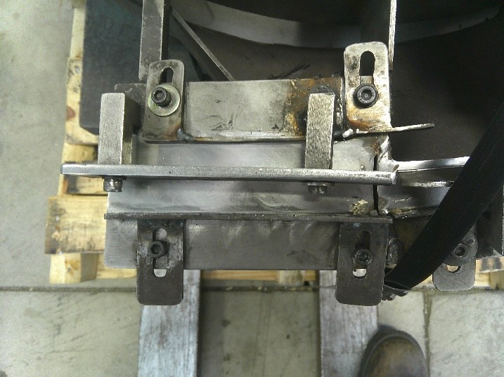
Bolt-In Tooling
Bolt-In Tooling can provide a removable or replaceable
tooling solution for applications where different
tooling configurations may be required. Depending on the
application, bolt-in tooling can make future
modification, replacement, maintenance, or retooling
easier without requiring permanent changes to the entire
feeder bowl.
Custom orientation tooling can be incorporated into a
new feeder or, when practical, integrated into an
existing feeder system.
▶
Bowls Running with Bolt-In Tooling
Modify an Existing Bowl for a New Part
Feeder Bowl Retooling
Existing feeder bowls can often be modified rather than
replaced.
New Orientation Tooling
Modification of Existing Tooling
Bolt-In Tooling
New Discharge Tooling
Flip Tooling
Changes for Larger or Smaller Parts
Updates for Revised Part Geometry
Feed-Rate Improvements
Improved Part Control at Discharge
Each existing feeder is evaluated individually to
determine whether retooling is practical for the new
application.
Restore & Extend Feeder Life
Complete Feeder Refurbishing
Full feeder refurbishing is available for existing
systems. Depending on the condition of the equipment,
refurbishing may include bowl restoration, tooling
repair, tooling modification, drive restoration,
replacement of worn components, cleaning, feed
adjustments, and updated mounting components.
Refurbishing can be a cost-effective option for
extending the usable life of an existing feeder system.
BeforeAfter
BeforeAfter
BeforeAfter
BeforeAfter
Added Protection, Quieter Operation & Longer Feeder
Life
Coatings
Urethane lining is available to help protect both the
feeder bowl and the parts being handled.
Our standard urethane option includes
urethane applied to the
bottom of the feeder bowl and the
bottom of the return pan. Urethane can
also be applied
up the feeder track when additional
wear protection or part protection is needed.
Protects the Feeder Bowl from Abrasion
— Helps reduce wear on the bowl bottom and other
high-contact areas.
Helps Prevent Bowl Damage — Reduces
impact on the bowl bottom, helping protect against
deformation, cracking, and premature wear.
Protects Parts from Damage —
Provides a softer contact surface when parts are
dumped into the bowl, helping reduce scratching,
denting, and other impact-related damage.
Reduces Noise — Helps absorb part
impact and vibration, making the feeder bowl quieter
during operation.
Improves Traction — Urethane can
help reduce slippage caused by oil or other surface
conditions, improving part movement through the
feeder.
Helps Defeat Hydrostatic Tension —
Urethane lining can help reduce sticking or holding
effects caused by liquid films between the part and
bowl surface.
Extends Usable Bowl Life — By
reducing impact, abrasion, and wear on the feeder
bowl, urethane can help extend the usable life of
the system.
Urethane Track Lining Available —
For applications requiring additional protection,
urethane can also be applied up the feeder track to
help protect both the parts and feeder tooling.
Standard urethane coverage includes the bowl bottom
and return pan bottom, with additional track
coverage available based on the application.
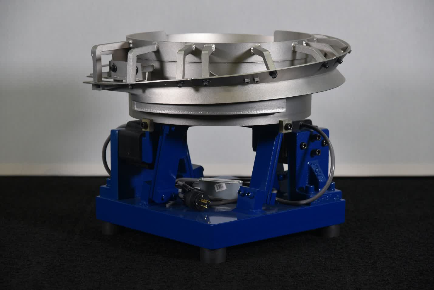
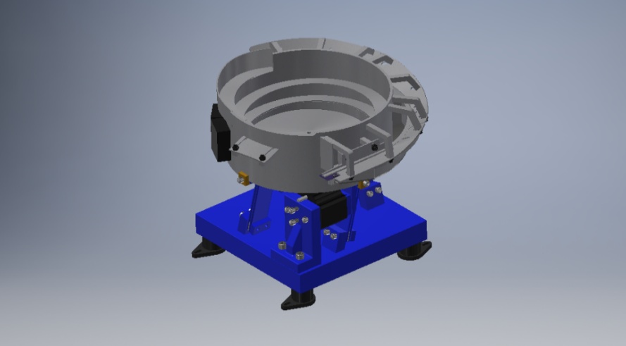
Feeder Mounting
Feeder Mounting & Vibration Isolation
Feeder systems are available with
thick, oversized rubber feet designed
to improve vibration isolation.
3-way adjustable foot cups provide
additional adjustment during installation and make
feeder positioning and alignment easier.
Rubber Feet & 3-Way Adjustable Foot Cups
Photo placeholder requested in content document.
Components for Feeding, Sensing & Automation Systems
Feeder Components & Automation Products
Attica Automation distributes a variety of components
used in vibratory feeding, part handling, sensing, and
automation applications.
Drive Unit Components
Vibratory Inline Components
Feeder Controllers
Sensors
Fiber Optics
Vision Cameras
Pneumatic Components
Air Jet Components & Systems
Replacement and Application-Specific Components
Components can be supplied for new equipment,
replacement parts, system upgrades, and existing feeder
applications.
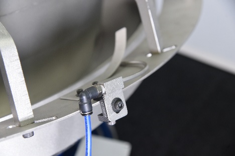
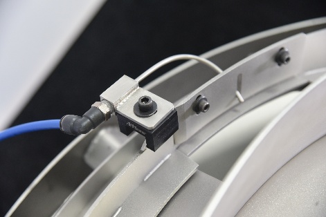
Compact Pneumatic Part Control
Air Jet Systems
Air jets are available for feeder bowl tooling and other
automation applications where controlled air is used to
assist with part orientation, rejection, separation, or
movement.
Available Air Jet Sizes
1/8" Hole Diameter Air Jet
3/16" Hole Diameter Air Jet
1/4" Hole Diameter Air Jet
Complete Air Jet Systems Can Include
Air Jet
Clamp
Clamp Fasteners
Quick-Connect Fittings
Air Manifolds
Pneumatic Hose
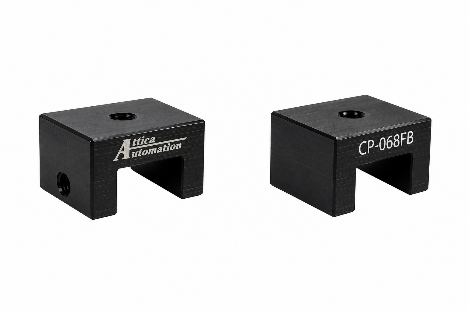
The clamp and Air Jet Tab style design allows the air
jet to be positioned and adjusted based on the
requirements of the application. Air jet systems can be
incorporated into new feeder systems or supplied as
individual components for existing equipment.
Various air jet sizes, fittings, manifolds, hoses, and
mounting components are available to suit the
requirements of the application.
Planning & Integration Support
Engineering & Layout Drawings
2D and 3D plan views are available with
every feeding system.
These drawings can assist with:
Machine layout
Automation integration
Feeder placement
Discharge positioning
Operator access
Guarding
Installation planning
Downstream equipment design
Support After Installation
On-Site Service
On-site service is available for feeder inspection,
troubleshooting, adjustment, installation support, and
system evaluation.
Bowl modifications and tooling fabrication are completed
at our facility and are not available as on-site
services.
Send Us Your Part
Not Sure Which Feeder You Need?
Choosing the correct feeder depends on much more than
one or two part dimensions. Send us the following
information and we can evaluate the application:
Part drawing
Part dimensions
Part weight
Part material
Photos of the Part
Required Orientation
Required Parts/Minute
Desired Discharge Height
Desired Discharge Direction
Details About Downstream Equipment
Sample Parts, When Available
Request a Feeder Evaluation
Our team can review your application and recommend
the appropriate feeder bowl size, tooling approach,
and overall feeding configuration.
The capacities listed on this website are intended to
help identify a starting point for feeder selection.
Actual feeder capacity and achievable production rate
depend on the complete application.
Screw Feeders, Washer Feeders, and Custom Feeders can
all be modified with application-specific tooling to
accommodate difficult part geometries and orientation
requirements. Bowl size, tooling, orientation method,
discharge configuration, and mounting can all be
customized to meet the requirements of the part and
production system.